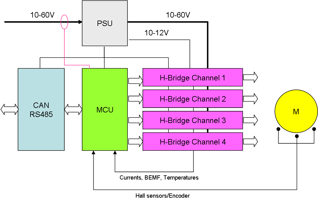
This is just a simple block diagram over MC4X design to illustrate it’s components and summarize the planned changes.
- More communication ports CAN and RS485. I hope to save some space and add more communication ports to support redundancy etc.
- New PSU based on TPS54x60 providing 14-60VIN or 10-16V in. Support 10-12V for Gate driver, 5V for Hall sensor and 3.3V for MCU.
- Added 2 temperature sensors on board located between MOSFET’s.
- New INA194 base current sensors.
- New SOP Advance MOSFET footprint will support both SOP-8 and SOP Advance allowing a wide range of MOSFET’s to be used.
- 4 separate channels with IR2103 as Gate driver.
- 4 separate high side current sensors.
- 4 separate BEMF sensors,
- Separate Hall Sensor port/Encoder port for additional positioning feed.
- Separate end point connectors for positioning calibration.
- Replace 2.57 pitch connectors with smaller 1.27 pitch
- Move main caps on board
- Change size to fit heat sink 100x40mm
- Stick to 15A design as objective, maybe increase to 20A depending on what PCB can manage
- Added pull-downs on PWM driver to avoid that gates are floating.
- Use JST Micro as channel connectors.
- New SWD Connector.
As for now I am still testing rev 1.0, so things are not written in stone. As for the new 3P controller I have put that on hold. I decided I wanted to do rev 1.1 of MC4X first. I do after all also have 3X coming in any day now.
I still have plenty of DRV10983 chips and boards so I will be playing around with that as well – we got plenty of motor fun coming up.
I have ordered separate test circuits for INA194 and this part is the only one that concerns me because of noise. I need to see if I can get a INA210 working on the existing design to test noise and noise filters.