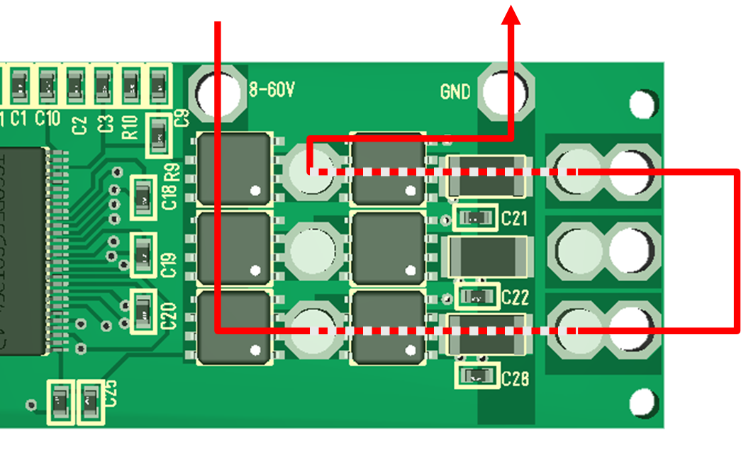
One of the main concern if you want to get 50A out is the current path and making sure it support 50A. The line in red show an actual example path that will have to support this. The entire driver area is only 40mm x 25mm.
60V in using top PCB lane down, over high side MOSFET, out through wire and back in through next channel and out through low side MOSFET and current shunt to GND. The weak link here is that I need 1mm x 4mm lanes to support 50A, so if I cover the lanes with solder tin it should be doable. If not I will start getting into problems around 10+ Ampere.
Looking at this design I can instantly see that I need a few more mm to create a solder lane on 60V and GND. But, after this mod I should actually stand a chance on currents.
Looking at signals I am not sure if I want to create interface between MCU and Gate Driver, or between Gate Driver and MOSFET. Assuming I do the last I will need the following:
- 8-60V
- 6 x PWM Signals
- 3 x PWM out signals
- 6 x current sense signals.
- In addition I should get 1.3 x temperature sensors for the MOSFET’s.
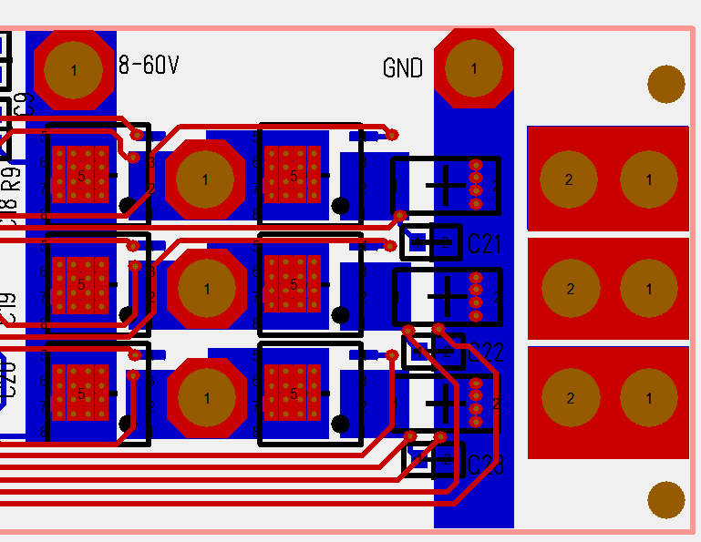
This pic show the actual routing of the driver. Notice the hole pads on the MOSFET’s, the short, effective lanes, but also the 4 tracks at bottom. The bottom tracks are current sensors and I grab both GND and Sensor at the same spot. This is quite important because you will get into funny ground signals if you grabbed ground from somewhere else – more convenient. I really should have had more layers to protect these signals from noise, but we will test. Looking at the PCB I realize I have the Space to move the GND hole to bottom just to make sure that 60V and GND wires are far apart to create less noise. But, I also like the idea of having them far away from current sensor tracks. This pic does not show the ground plane.
As for effect I calculate 4.75W for 50A and 1.9mOhm. As this is split on 3 transistors I actually hope to get away without heat-sinks. The same goes for the Shunt. 0.001R will be 2.5W, but again as this is 3-phase it should be split by 3. As mentioned the MOSFET’s support 160A, but I stand no chanse of supporting that. This will regardless be interesting to test, but I have a bit of work left before I get there. This controller might be my x-mas fun.