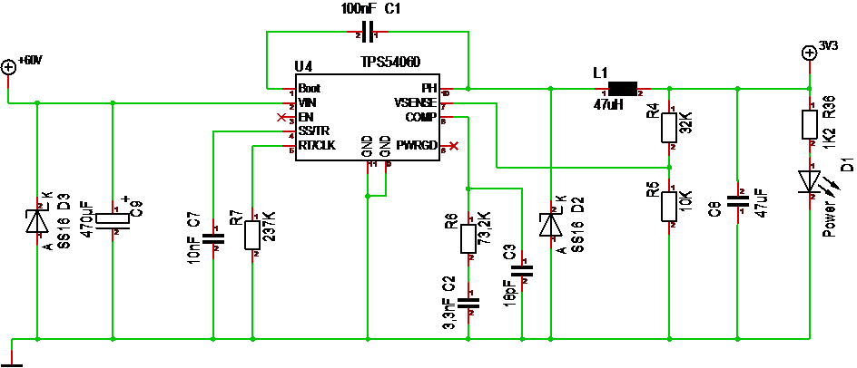
This is my first attempt on a 60V to 3.3V DC/DC converter. I am using the reference diagram for TPS54060 with a few modifications.
Starting at left I use a SS16 Shotky diode + a 1000uF since this is for a motor driver. You can otherwise use far less capacitance on the input. I left EN and PWRGD floating – EN is used to set under voltage shut down, while PWRGD signal if there is an error. L1 and C8 is the PWM filter and at right you have a standard Led to indicate power. C7,R7,C2,R6 and C3 are just from the reference diagram. Their values impact things like switching frequency. I need to read the datasheet properly and doublecheck with what others have done, so I can’t guarantee that this will work – but, we can give it a try!
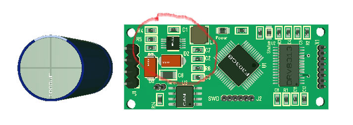
This 3D model is the first attempt of routing a simple version of a DRV8313 60V BLDC Controller. This board is 50 x 20 mm, so it is really small and you can see the DC/DC in the red circle. I drew the 1000uF on the outside because it will be mounted as an extension fo the board. I also decided to use a coil at the size of 2x 1206 package. I should mention that all components here are on top-side. I will return to the BLDC controller itself later. This is DRV8313 With hall sensors only. This is a simpler design than the one I mentioned earlier as it lack the super-cap, current sensors and Serial memory, but it still have hall sensors. Looking at the density of the Board I probably need to extend the length a few mm as I finish it – lets see. To add the missing features I probably need another 2 cm – not sure.
I was hoping for even smaller Space on the DC/DC, but the number of components and the size of those SS16 diodes drags it up a bit, but draw a square 15 x 15 mm on a paper and you realize how small this actually is – and this is a 60V to 3.3 DC/DC delivering 0.5 to 1A. This design is 0.5A, but I can swap out with TPS54160 to get ca 1A if I need to.