I fancied testing my MC4X15A motor controller as the driver for a PSU. The code is very simple as I bit-bang a PWM with 50% duty and use filter consisting of a 100uH coil and 1000uF capacitor.
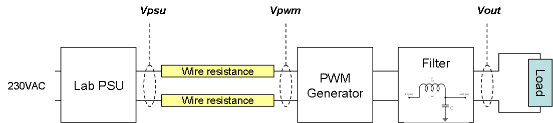
The result was quite good. I did however notice some input ripple. As I also scoped the Lab PSU output I saw a much, much smaller of the same ripple. Replacing the cables the input ripple improved. What happens is that due to wire resistance we get a power drop as we start drawing current. The drop was actually 1V before I changed cable.
My home made little PSU actually worked quite well. I would have needed a better filter, but output ripple was not horrible and if I had put a decent driver and wiring it probably would have disappeared.
I used 100uH, but a real PSU would use something like 10uH to get a lower power drop in the filter. My motor controller hold it’s ground at 1A, but temperature on HEXFET’s started to rise at 1,2A. I need to work on cooling obviously.