I desperately need more lab PSU’s and I have a bunch of LM723 and TIP3055 transistors that are excellent for creating an old-fashioned Linear PSU module. Thinking a bit ahead I want to create the analogue regulator as a small, separate module with knobs on the front, heat-sink & transistors on the back and connectors on the side.
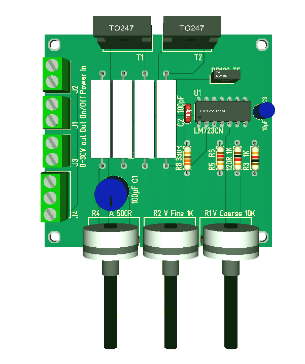
The 3D model above is an early draft on 70 x 75mm. I am using hole througt Components on this one to enable hobbyists to grab a PCB and solder them up themselves to save cost. Adding a Voltage/Ampere meter is easy because I just use a module like this one (or similar):
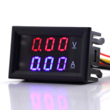
They cost less than 5.- USD and they work well. I add no other led’s or display, but I add two power switches – one for input and one separate for output.
I am also using 2 x TIP3055 that technically enable 30A together, but PCB lanes and current limit is scaled for max 10A. The following block diagram show the complete PSU.

The mains are basically a 36V/10A DC-DC regulator. These comes at a decent cost with CE/FCC approval that is needed for 48V and higher. What is remaining is to find a project box and we have a nice Lab PSU.
to be continued…