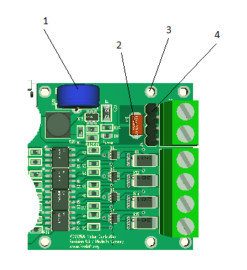
Earlier I had a BEMF issue with my smaller motor controller, so I have been reading up on other peoples experience and solutions to design my own. What I came up with is 3 changes on the MC4X15A.
- Added a 0.33F super capacitor on 3.3V protected by a TVS (on the back) at ca 4V. The supercap will absorb any spike that reaches 3.3V and it will allow the MCU to survive a power dip of several seconds. The later is great as it allow the MCU to monitor and record a Power dip.
- Protecting the main PSU with a nasty TVS to avoid that it spikes out of control. This will be set just a few volts higher than the max voltage. This diode is also protecting the surroundings as we have no galvanic issolation on this one. This should also protect against wrong polarity.
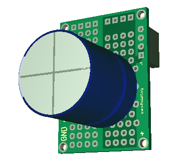
- I need more capacitors on the PSU, but I have no room for these. I also wanted a battery adapter option. I decided to make room for an adapter board supported by 4 extra M2 screw holes that either can carry extra capacitors or a battery adapter. The example (below) show a 10,000uF/50V capacitor, but notice that this in reality is a vero board so you can add your own design of capacitors.
-
The connector is a standard 2.54 pitch pin header enabling the adapter board to be engineered on a piece of vero-board. I didn’t want to lock to a specific capacitor at this point so vero-board is fine. This also allows a variety of simpler solutions if I don’t want to use the adapter Board.
I am still not confident that I got everything about BEMF 100% correct, but I will work on that. I might need a combination of capacitors as well as more diodes – not sure. And I need to test this so it will be a few exploding capacitors before I am done :).