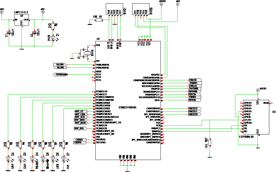
The schematics for the main MCU parts. This still uses the ESP-03 for Wifi. I intend to replace that with ESP-12 and ESP-01. The m,ain reason is availability & cost, but also the access to Reset pin that is not available on ESP-03.
At right bottom you have a 6 status leds, one for each communication port. The 7th led is showing 3.3V Power. On top you have my SWD Connector.
I need to do a review of pull-up/down resistors. Usually I don’t add them because the MCU have internal ones that can be added in software. But, you need to consider what happens during the start-up while the pins are floating. I added a pull-down on ch_pd to force ESP-03 to be switched off until software switch it on. I need to add the same on the NRF Circuit to avoid that it og wild transmitting junk during start-up.