LoRa Units

Small units to communicate over radio is not exactly new. We are well used to 2.4Ghz modules that cover both 100m and even 1km ranges. LoRa stand for Long Range and some of the units have very impressive parameters.

This little fellow is 20x14mm and can communicate over 6,5km using 850-930Mhz. It’s brother E22-400M22S cover 410-493Mhz and it’s bigger brothers M30S cover 12km with 300Kbps data speed. The M22S uses ca 100mA transmitting while the more powerfully M30S uses 650mA for 12km.

These are LoRa (Long Range RF Tranceivers) for the global LoRaWAN standard and cost ca 8.- USD.


Ra02 is smaller, cover up to 10km and uses 433Mhz. This is also an older unit costing <4.-USD.

Usageand interfacing to these are rather straight forward with UART or SPI, and the radio range versus cost and power usage makes the excellent for various sensors and low bandwidt data-links where distance is of importance. Do however check regulations in your country before using these because some countries have license regulations and restrictions on usage.

Wifi Module

I moved CAN to the same place as the X Hub and will be using this from now. Added jumpers for RS485 vs UART out. The rest is as before:

  • ESP32
  • RPI connector using SPI
  • CAN port
  • RS485/UART port
  • USB Serial/Programming port.
  • 5 x Sensor ports.

The X Hub is a better match for Raspberry PI, but this can replace Raspberry PI to get Wifi and with the CAN port you can stack up IO as much as you want.

RPI X Hub

Routing a PCB is actually a bit of work, but I enjoy doing it a few hours early morning and late evening. It is easy to pick up and then just leave, and over 1-2 weeks I usually get a design done like this. It is always a special feeling to suddenly find that you have no more green lines and can start the checks. I am actually not fully finished here as I need to modify the Micro SD package + I would also like to replace the 1.27 pitch headers with connectors 3D because I need to adjust their distance to the edge. I also need to check my alternatives on footprint for the Super capacitor and battery.  I ditched the GPIO header because I have only 3 pins left and will see if I can route them out as leds. But, this looks good!

This is the PCB the way I usually see it in the EDA without the ground plane.

This is the PCB the way I usually see it in the EDA without the ground plane.

I use ground pane for connections to ground to avoid ground loops, but the EDA have an error that it does not warn me about isolated icelands. So I remove components and top layer and copy it to MS Pain using fill. That will indicate what icelands that are left. In this case it was several that I managed to change so they got connected. The small ones left in the middle has no connections so they can just be left.

I will do the last check later today and off we go – next time you see this will be the actual PCB in 6-8 weeks. I had a bit of challenge finding a name on this, but decided to call it “X Hub”.

RPI Hat – 32 x IO Upgrade

This is the 3D of a new 1.1 that I never ordered. The only difference from 1.0 is the TVS diods and a few mechanical adjustments. I will remove the address logic at top right, replace the SWD, replace the power connector and move the inner 16 IO ports to the edges while I also add CAN and USB.


These block diagrams are simple, but they are part of how I like to document the modules, so I like maintaining them because they illustrate the Inventory of the Boards.

One remaining decision is where to put the CAN port because they should be at the same position on all boards since this is the main control bus. At present top left corner is a candidate, but I need to make that the same on all Hat’s. The RPI Header is not a pri 1 on these Hat’s. I will leave the RPI header on if possible. It also make sense having one side with no connectors out.

As for the 32 x IO board I think I have covered that before. These are GPIO signals exposed “as is” with a TVS diode to give the MCU some protection. They uses a 5V design, but I will allow a separate 5V so that we can feed Servo’s from a different PSU source. That alone provide a huge protection from misbehaving Servo’s and it allows Servo Power to be 12 V if needed. 

I probably need a weeks time re-routing this board. At present I plan to do a lot of these boards before x-mas, but let’s see.

This board have extra mounting holes for Raspberry PI Zero W. I am not bothered about these because ESP32 privide a low cost Wifi alternative. I don’t want a Linux board for the sake of having a Linux board. But, Raspberry PI 3 A/B+ with it’s 4 x 64 bit MCU, Camera and HMI capabilities makes a lot of sense if you need to dig into some of it’s capabilities.

I also have a ESP32 version of this board that in many ways are superior because you get ports and Wifi on the same board. I have to upgrade that as well and I wonder if I should follow the same RPI format – the board is about the same size, just a bit different. As great as ESP32 is it can however not really compete with a F405 on IO capabilities. One Word about ESP32 is that I need to check out it’s CAN capabilities before I do this.

Stay tuned!

Updated RPI Hat Base


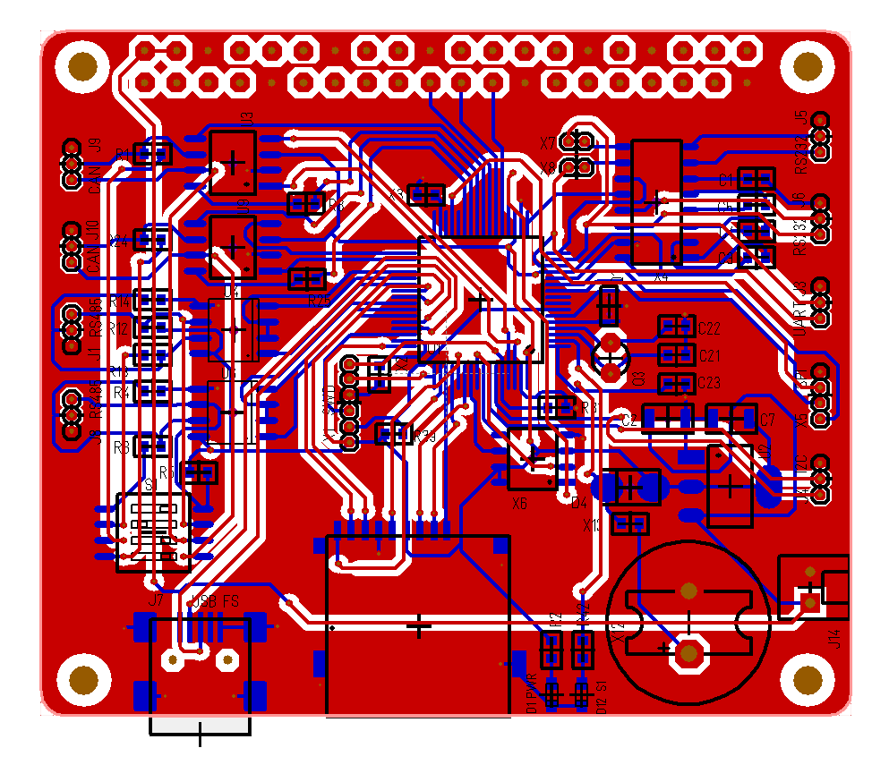
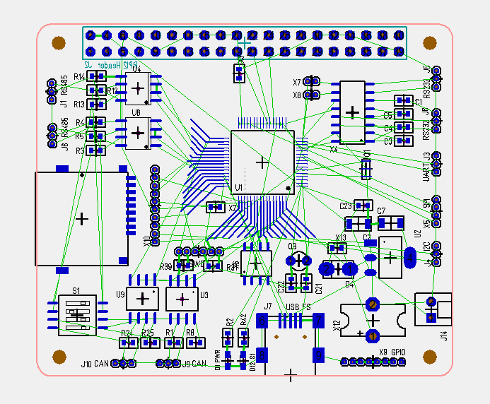
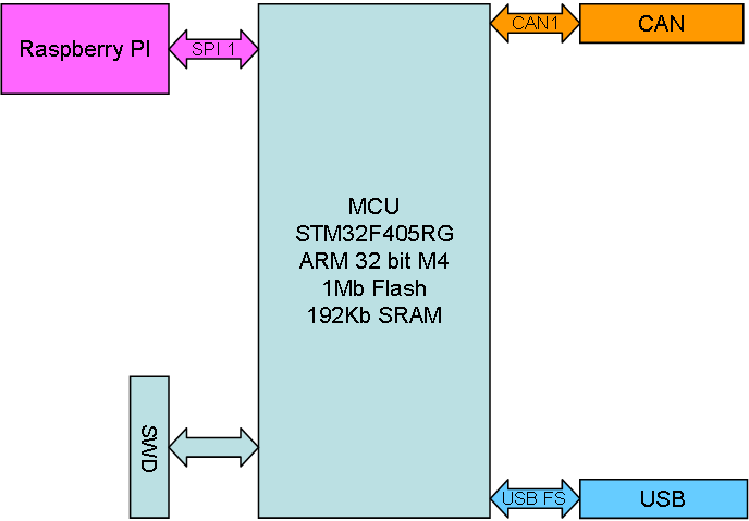
This rather boring drawing represent my new base for a Hat. Notice that I have removed the addressing scheme from the old ones, added USB and CAN as standard as well as Raspberry PI Hat form and SPI to communicate with the PI.

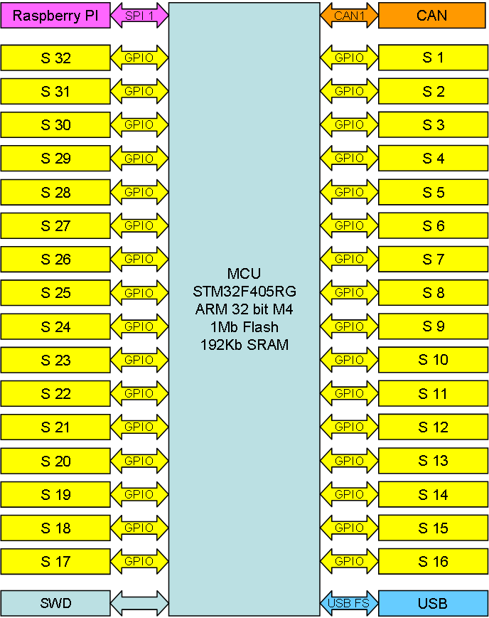
F405 is so fast that we can use higher SPI speed (ca 45Mbps) and I think we can achieve ca 30Mbps full duplex data, which basically is 60Mbps comparable to other standards. I can soft-switch on a SPI bus sending to one device and receiving from another creating a true device to device data stream. Removing the address scheme means that any device can become “Network Master” controlling this. I will return to the Software design tricks here in a different article.

I have one challenge here – how to identify a device? F405 have a Random Number Generator allowing me a safe way to guarantee that two devices behave different. Each of the F405’s also have a unique 96 bit ID. Using this in combination I can manage to tell the network master that we have a new device and get it allocated a time slot. I know F405 is up for the job, but I am more concerned about Raspberry PI due to the Linux core. The SPI on the Broadcom do not have the same support as you have on a F405, but lets see what we can achieve.

CAN is the actual control bus here. Can is excellent as it also allow up to 1km cable between devices. It does not cover the same speed as a SPI, but it is a classic in control systems. I am as many of you know a big fan of RS485, but CAN have it’s advantages as well. It is a bit more difficult to wire, but used here as a backbone net on short distances it is excellent.

USB is a bit new to me, but this is basically a high speed 1:1 serial port. It allows me to connect and power the device stand-alone from a PC. 5V from USB is connected to 5V on Raspberry PI, so this will power RPI and the rest of the stack as well.

I use a new 6 pin SWD connector here. I have described this earlier. I am very happy with my old 2×5 pin, but I mostly only used 3 pins and it added a lot of complexity. I tried a JST Micro connector, but will return to a simpler 1.27 pitch header and an external adapter card to convert to ST.Link/V2 with a Boot and Reset button on the adapter. I also had an UART on the old one, but that is expensive (in terms of pins) and I never used it.

This will be my base for a series of board that I plan.

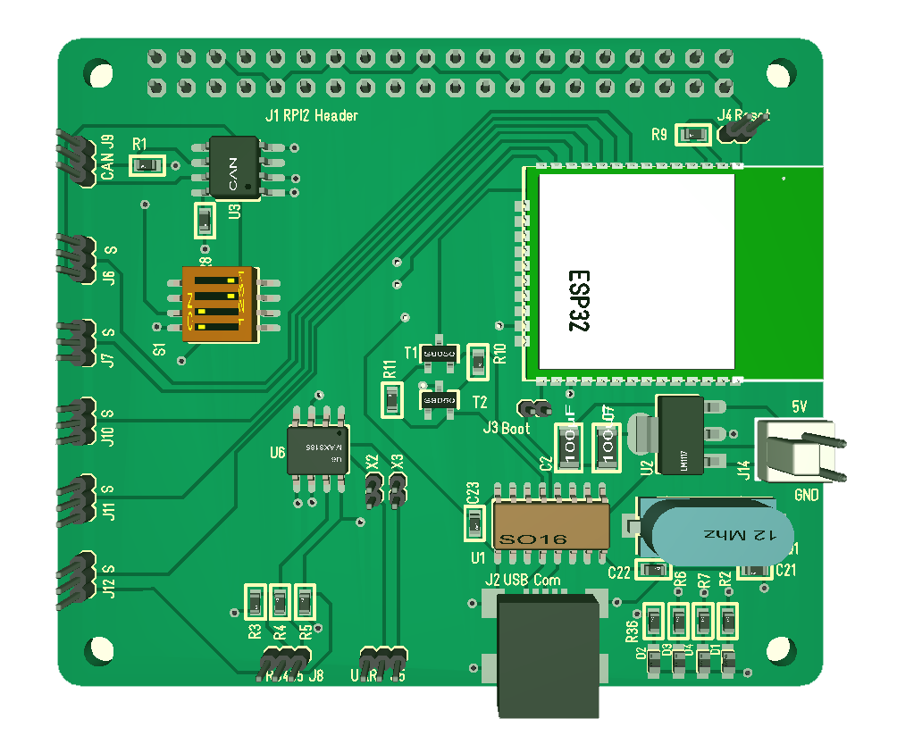
  • 1 – Wifi board based on ESP32. This is intended as a low cost Wifi option compared to Raspberry PI. ESP32 is in most cases sufficient + it offer a CAN and RS485 etc.
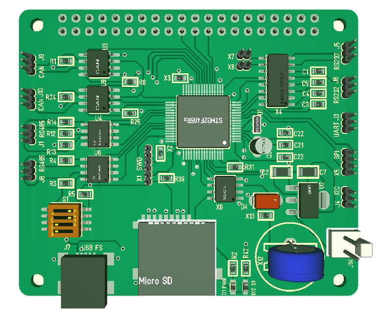
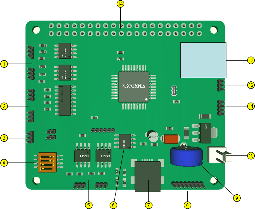
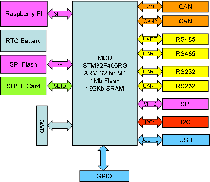
  • 2 – Communication Hub. This is covered in my previous article and will soon be ready. Communication options are basically so basic to any system that I find myself doing a lot of these variants. This includes a SD Card, Flash memory, RTC Clock, 2xCAN, 2xRS485, 2xRS232, SPI, I2C and USB making it a very powerfully Hub.

The next ones are an upgrade of earlier Hat’s.

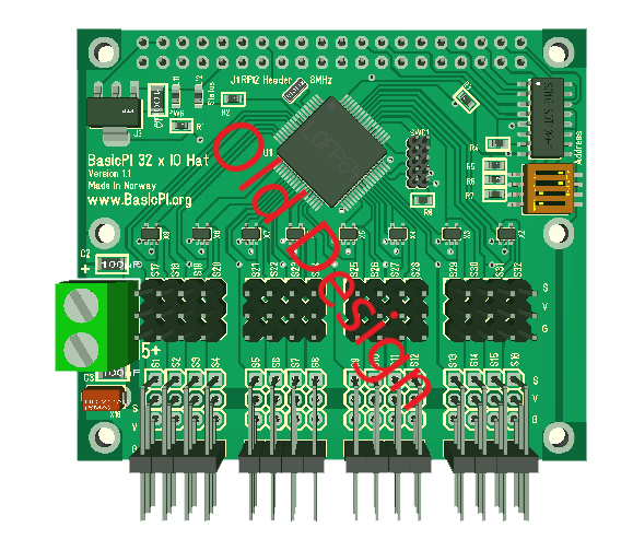
  • 32 channel Servo/IO Hat. This is one of my simplest, but yet most usable designs. STM32F405 is so powerfully that we get 32 ports in Servo format with +/- and a signal to drive a Servo, Digital In, Digital out, Analogue, In, Analogue Out, PWM Out, PWM In etc. I actually planned a GPIO board at one point, but realized that this board is so much more powerfully. And with 3 sides for connectors we should be able to do 32 channels a bit better than my existing board.
  • DC Motor Hat. I made a 8x DC Motor Hat and plan to extend this. My existing board had some IO + 8x DC H-bridges. I will see how many ports I now can make.
  • 3-Phase Motor Hat. DRV8313 is excellent for driving small 3-phase motors, so I want at least 3 motors – maybe more together with some IO. The focus is low speed position systems so the IO options will reflect this.
  • 5-wire Stepper Motor Hat. It is some excellent, low cost (1 USD) stepper motors around that need a decent support board. Using ULN2003 I can support 7 steppers with 4 chips. This board need 2.54 pitch connectors since they come with the motors, but with 3 edges I believe that is doable.
  • 4-wrire Stepper Motor Hat to drive more classic stepper drivers. In this case I plan 3 steppers up to ca 3A – standard for a 3D printer/CNC.
  • High resolution Analogue input board. 8×24 bit ADC w/30Kbps speed ADC’s are available low cost and this needs a Hat.
  • PWM Driver – 24V/1A. In fact this probably can be achieved in combination (or as a variant) of my 3-Phase Hat. Using DRV8313 and 3 x chips I basically have 12 x PWM channels.
  • Heavy Stepper Motor Driver (MC4X60V50A) – I need CAN on this to be able to control it, but I do not want this directly into a stack.
  • Heavy 3-phase Motor Driver. MC3P60V50A is a bit slipper than it’s 4X variant and focus on 3 Phase motors only. It has the same challenges that it can’t be directly connected on the stack.
  • Isolated CAN Hub. Heavy motor drivers and long distances have some challenges where we need to consider isolation. I tested ADM chips just to discover that they get very hot, so I want to explore a different path. Due to size I am happy with 2 x CAN per Hat.

Most of this is consolidation of work I have done on this blog before, so it is not as much work as first impression might suggest. I am in general not scared of Electronics because I find it very easy and relaxing to do an hour now and then, and over time I achieve a lot. Writing SW for all of this is a larger challenge, but I only intend to make the basis so others can start programming this time.

I sadly need to make one assumption – the state of Norway plan to put MVA and handling fee on all import. This means that a small package that now cost me 10.- USD suddenly will cost ca 30.- USD extra in tax and bullshit fee’s. It will become a limiter on what I can afford to do in here. My only alternative is to start selling board so I can afford to continue. Without this I fear the electronics part of this blog will come to an end.

Thanks for reading my Saturday morning ranting 🙂

RPI Hub PCB Layout

A bit different picture this time. This show the component layout and the green lines are the PCB lanes I need to make. I have added the package for the Micro SD Card holder, but I still only use 1.27 pitch headers for the Micro JST connectors. GPIO Header is not wired in schematics yet. The exercise here is to have as little crossing green lines as possible to make PCB layout smoother, but this starts to look promissing.

I added a 10 pin 1.27 connector for SD card. It gives me the option to use this as a 9 pin IO connector + the header make signals available on both sides.

I will start to upgrade my other RPI hat’s once this is done. I have a 32 port Servo controller + 8 port DC-motor controller, but I also want to move on with a 7 port stepper/PWM controller. Have them all as RPI-Hat’s, stand-alone USB or CANbus plug-in’s.

I want to use STM32F405RG, but as you know this can also use STM32F105RB by just replacing 2 capacitors with 0R. F405 and USB means this becomes very available for Python programmers etc.

I am not sure about the SWD connector. I have replaced the 2×5 pin with a 1×6 pin. The 6th pin is 3.3V. I tried using JST Micro connector as SWD and it worked, but I must admit that is much easier to plug in a adapter board on a header. The JST connectors are hard to mount and remove again + wiring on a SWD is a bit critical.

9 port RPI Hub 3D

I like doing these early mock-up’s of PCB’s and adjust schematics because they tell me what I can achieve with pins and space. This is the new RPI Hub I am working on. The details will change, but it looks doable.

  1. 2 x RS485
  2. 2 x RS232
  3. 1 x TTL UART (consume a RS232 port if used)
  4. Terminal switches for RS485/CAN
  5. 2 x CAN
  6. 1 x Serial Flash
  7. 1 x USB
  8. GPIO Expansion Ports
  9. Super-Cap or Battery for RTC
  10. External power connector
  11. 1 x SPI port
  12. 1 x I2C port
  13. Micro-SD Card (MMC).
  14. RPI 2/3 Header

The Hat is in the format of a Raspberry PI Hat. The Hat can be used stand-alone powever by USB (or external), or as a Raspberry PI Hat. As mentioned this is an early mock-up so the actual PCB will change. It will probably take me another week before I order this, so I expect to have

I am also trying rounded corners this time, lets see how that goes. As for usage – this is basically a add-on module for a mobile control system that can operate stand-alone, in a bus or at the back of a Raspberry PI 3A+ or Raspberry PI 3B+ etc.

ST/CubeMX Quality Issues

I really like CubeMX for what it tries to do, but having used it for a while on different MCU’s I also realize that the code it generate is not very mature. On some MCU’s it works well, on others it don’t even compile or as in the example of STM32F105RB temporary brick the MCU. The F105 is also part OpenOCD since CoIDE behaves better.

This creates an issue because I am not sure wherever to continue with CubeMX drivers or roll back to old ones. Luckily I do not depend directly on either as I use my own HAL wrapping in C++, but I need a driver library to fuel this wrapper and it is not really a path forward to use an old library that is going obsolete.

Moving on to IDE discussion SW4STM32 is a possible path forward as IDE, but I am not convinced. I will use it because it integrate nicely with CubeMX making it an easy path for HW testing, but I am far from convinced I will use it for actual Projects.

EmBitz 1.11 looks very promissing being build on Code::Blocks. The only libraries supported out of the box is however the old standard libraries, but EmBitz does also support other MCU’s. I am however not sure exactly how active this project is + I want to go back and investigate using Code::Blocks itself.

9 Port Communication Hub

Updated Article!

I am quite happy with the 5 port Com Hat I made for Raspberry PI, but I want to use a STM32F405RG and maximize usage of all it’s IO capabilities. This will be an upgraded Hat with a few more features included:

  • Replace F105 with the faster and more capable F405 including 1Mb Flash, 192Kb SRAM, ticking at 168Mhz with an ARM 32-bit M4 core. This change will allow Python and .NET to be used as well.
  • Add a RTC w/battery connector.
  • Add a SPI Flash
  • Add a SD/TF Card. I will use a 4 bit MMC version.
  • 2 x CAN ports as before
  • 4 x Serial ports. 2xRS485, 2x RS232 or TTL. My first thought is 2 x RS485, 2 x RS232 and 1 x TTL, but lets see.
  • 1 x SPI port
  • 1 x I2C ports
  • SPI, I2C and available pins as separate extension port. Maybe even throw in a UART TTL here.
  • 1 x USB
  • Limit leds to 1 or 2 pin’s max. We can signal through blink sequences.

I have the pins to do this, so it remains to se if the space of a Raspberry PI Hat will allow for this. I will need to use 3 sides with JST Micro connectors for this one.

PSU here will either be USB or RPI Connector, but I will add a 2 pin 5V power as well.


Bricked STM32F105RB

I am a heavy user of STM32F105RB/RC, but I have not used it much with SW4STM32 before. SW4STM32 (System Workbench for STM32) or ac6wb as it also is called is based on eclipse and uses OpenOCD to connect to the MCU’s Serial debugger. A few days ago while testing CANUSB I noticed problems. First on one MCU, then on a 2nd, 3rd, 4rth and 5th as I just continued bricking MCU’s to rule out that it was the batch.

The library and code here is generated with CubeMX, so I am not sure if it is the generated code, OpenOCD or SW4STM32 that trigger the problem.

I just brought the original MCU back simply by erasing flash with STM32 ST-Link Utility. It worked fine with CoIDE, but as soon as I try SW4STM32 OpenOCD will brick it. Some times it works fine a few times before it suddenly break and I need to bring it back with STM32 ST-Link Utility.

Adding to the story – I downloaded the code generated by CubeMX manually and the same happened. OpenOCD ir SW4STM32 do have a bug because it is not capable of programming the MCU while CoIDE has no problems. But, even STM32 ST-Link Utility cannot connect after code is started, so I need to do a connect under reset – meaning the problem here is the code generated from CubeMX.

This is not the first time CubeMX hits me in the face with a non-mature code example. The tool is great, but I am not able to trust it’s code at precent.

I tried to generate a test project from EmBitz as well, but that uses old libraries for a start and it don’t even compile as it miss the main header file. It just proves to me that I need to manually assemble the HAL myself file for file. I would like to use the newer CubeMX, but I do question their maturity Level.

It also raises a question wherever I should just move on to STM32F405RG. F105 is a real good MCU, but it is less supported than F103 and F405. It cost 50% of a F405, but it is nothing a F105 does that F405 can’t do better. In schematics it is only 2 capacitors that differ the design and they are drop in replacement of each-other on electric levels – obviously F105 have a few less capabilities than F405. I am not ready to give in on F105 just yet, but I am reaching a point where the added cost has to be weighted against time usage and support. And the only argument so far in favor of STM32F105 is that it cost a bit less than F405.