Radio/4G/GSM Hat

I drafted a GSM/GPS module some time ago, but I never ordered it as I decided to ditch that PLC design and pick up a smaller footprint. Time has changed so I want to make a new approach.

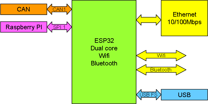
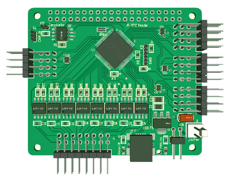
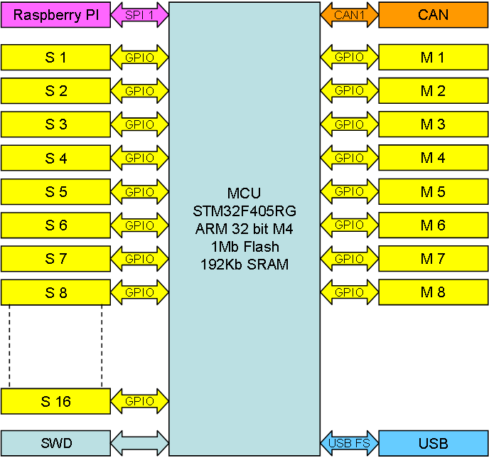
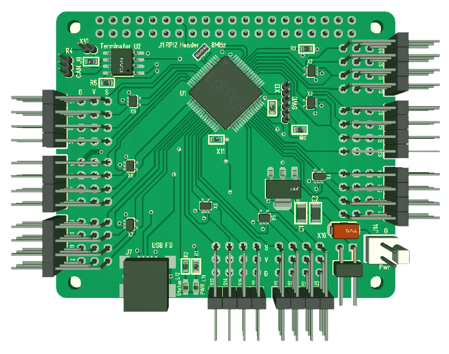
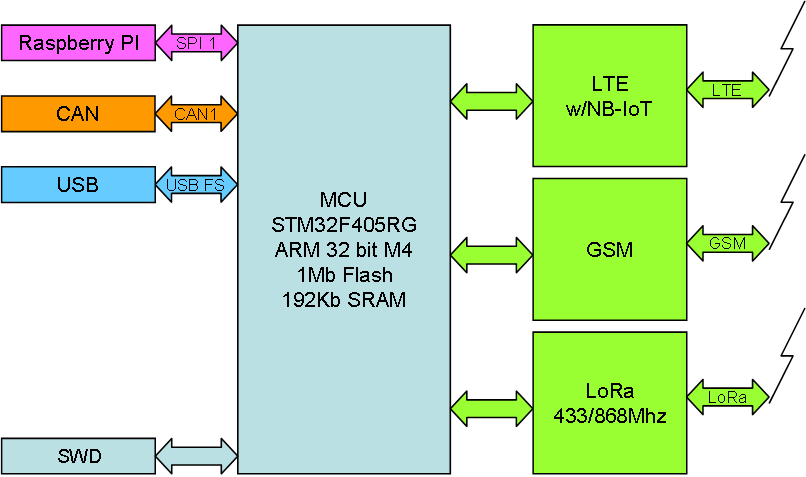
Using STM32F405RG as core I want to add NB-IoT, LoRa and GPS capabilities.

NB-IoT is a new 4G service allowing 300Kbps, low cost data links over mobile networks.

LoRa is Long Range radio and cover 433Mhz and 868Mhz modules to communicate up to 12 km with 300kbps speed.

GPS is as you know a system using satellites to detect position.

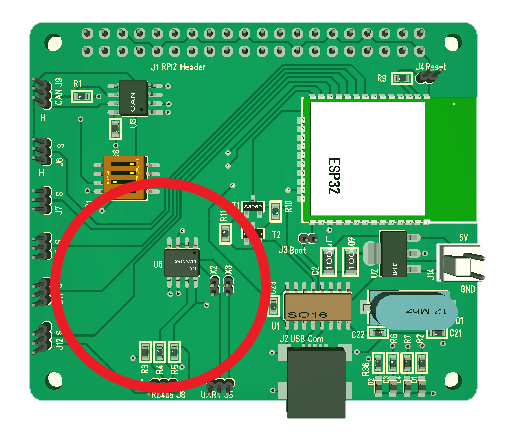
I want to make Raspberry PI Hat’s with these breakout’s. Looking into the practicalities I probably need 2 hat’s for this due to space restrictions. All three of these will need high frequency antennas, so I might for that reason alone need 3 Hat’s. Let’s see where we end up.

A natural infrastructure is that you use NB-IoT to reach remote places and then WiFi or LoRa locally. Both Wifi and LoRa units are secure these days. My real reasons for doing this has to be secret as I basically need these components for a test-bed/prototype and this is a great opportunity to add components to a modular Control system that is excellent for home automation and prototyping.


Ethernet/Wifi Hat

I want an Ethernet module to by list of boards. I can always use Raspberry PI 2/3, but I would still like to make my own as well. In the past I have used W5500 a few times, but this time I want to dig into ESP32.

ESP32 already have the TCP/IP stack, it has Wifi/Bluetooth and an Ethernet interface. A few vendors have also show schematics for Ethernet on ESP32, so it makes sense upgrading my ESP32 Hat with Ethernet. I do have the space if I drop the RS485 etc. A quick check also tell me that I have the pins as well.

The Raspberry PI Header can be sacrificed if I need to. CAN is the backbone bus and this is most attractive if I want to replace Raspberry PI as Wifi/Ethernet GW.

This Hat is not a priority, but I will make it at some point.

STM32F405RG Tester

One of the challenges I face is that batches with MCU’s from Asia are dodgy. This has been specially bad on STM32F405RG so I want to make myself a MCU tester for Rx and Cx series. I just tried to wire one and it kind-off works, but SWD wiring get to dodgy so I need to make a proper PCB.

I have one of these laying around and have ordered a few more, but I need to remove the breakout board and mount it on a dedicated test PCB.

  • Power and ground connected. Using a USB as power connector.
  • VCAP capacitors with switch so I can test both STM32F1 and STM32F4.
  • Led on all pins
  • Proper SWD connector – short cables. Rather than the 1.27 header I can use a 2.54 and plug ST-Ling/V2 straight on the board.
  • 8 or 16Mhz x-tal mounted.
  • UART1 connected on a connector so I can run a standard application and display some test IO.
  • Header rows for all pins.

It is so many functions on a STM32FxxxRx MCU that it is difficult to test them all, but the application above will get me airborne knowing that the MCU looks decent before I solder it on.

A STM32F405RG has a factory price of 5.8.- USD from ST and I would gladly pay that price, but before I receive a MCU from a distributor it cost me 17.- USD all included. So I use Asian sources. The challenge is that MCU factories also are in Asia and many people earn a few extra bucks by selling factory rejects. For prototyping many of these are “ok”, but then you have those that are not.

I faced the same issue with MOSFET’s earlier, but discovered that it was cheaper getting the MOSFET’s from Arrow so I had a bit of luck. Buying a STM32F405RG from Asia you get them down in 3.8.- USD these days. With a tester I can test them straight away and slam bad batches by claiming my money back and avoid the loss.

I will need to build the tester for each MCU, but I can probably sell of a few of these testers as well because I am not the only hobbyist or professional needing this and this type of equipment do cost money.

In fact, I can probably use 1-2 MCU’s to auto-test a 3rd MCU, but that us fun for later.


XPortHub on Raspberry PI 3A+

XPortHub feeding from Raspberry PI 3 A+ this time. 2nd board and 3rd MCU. The 1st MCU started behaving strange, so added a 2nd that did not work at all. Finally ripped off an old good one and we have a working board. Basically I need to make myself a tester for these MCU’s. Regardless, running fine at 168Mhz with USB working.

 This board can as mentioned be used stand-alone powered by USB, as an add-on to Raspberry PI or as a module in a stack of similar board interconnected with CAN.

New PCB’s

The first 2 Hat’s of my new series arriving – I paid for the fast track because I will be assembling and testing these over x-mas. The PCB at left (above) and below is the XPortHub, the other is the ESP32 based Wifi Hat. The picture below is on top of a Raspberry PI 3 A+ and mechanics fits perfectly. Also the Micro SD card was perfect, so this looks good.

7x 5 wire Stepper Hat

This board is a bit misleading  because I am using the wrong connectors to mock up an early 3D. The actual connectors are right angle and a bit wider, but testing on a paper print it seems that I have just about the size I need. Below is a picture of the Stepper Motor this targets.

These Steppers cost ca 1.- USD and they took me completely by surprise. As I started one of them it was moving slow, smooth and absolutely soundless far more powerfully than I expected. You get a lot for 1.- USD on these to be honest.

8 x DC Motor Hat

Revision 1.1 of my 8x DC Motor Hat. Basically this is 8 x DC Motors and 16 x IO/Servo, but the IO ports are 5V only. Differences from revision 1.0 are;

  • STM32F405RG 168Mhz 32 bit ARM M4, 192Kb SRAM, 1Mb Flash.
  • CAN bus
  • Removed addressing.
  • USB
  • Separate power connector.
  • 8 x DC Motor ports 5-12V with separate PSU.
  • 16 x IO ports. 5V.

This module was basically created because I wanted to control a robot arm I have around. This is a toy with 5 x DC motors, but using the IO I was hoping to create some position or end-stops so I could control it better. Just fun.


New 32 x IO/Servo Hat

Revision 1.3 of my 32xIO/Servo Hat. This export 32 of the GPIO pins using a Signal, V+, GND header common for Servo ports. V+ can be separate or use 5V from USB.

This version uses the 3 edges to get all 32 IO’s available on the edge of the board. It does in addition add the CAN port (top left) and address pins are removed.

STM32F105RB is also replaced with STM32F405RG and I added the USB port. USB is handy for many reasons, but it makes it convenient to download MicroPython and then use USB as programming port for Python scripts.

I need to return to MicroPython because porting that down will be a large task. I am confident I can get it compiled and ported fast, but I also need to extend the libraries to support firmware available on the Boards.