Train Control System – Utility driver

Early mornig fun. Just changed the driver to use USB (CH340G) and added a separate 12V supply and some jumpers to select power Source. It can now be driven from 12V or 5V and you can use 12V for PWM’s while using USB 5V for ESP32 etc to have some isolation. Also added pull-up for Boot/Reset and jumper to use them.

A bit more labels and TVS diodes on the left 12 x IO and we’re done. I must admit that this little fellow will see some usage.

My 12 legged robot comes to mine as this is a very small, compact alternative for this one. But, I need some experience with using ESP32 before I continue.

Model Train Utility Driver – Part 2

We have a lot of space on the Utility Driver, so I can afford to add some TVS diodes on the ports that go directly out. These are 3.3V and can only handle 6-12mA out – basically they can just about drive a Led with some care.

I also need to change UART0 pins + I would like to replace the RS485 port with an USB powered by CH340G – in which case the LM1117 can have a jumper selecting if it is powering 3.3V from USB or 12V. The advantage of this is that I get the Boot pin free.

I also need to add a pull-up on Reset and a way to Reset the ESP32.

And obviously – a power Led.

ESP32 – Downloading Firmware

I found this schematics on esp32.com forum. I will add pull-up resistors on GPIO0 and EN as well as route them to the extension bus on the TCS. I also need to change pins so I use pin 34/35 as UART0.

UARTS can be assigned to any GPIO pins, but in this case I need to know where it is after Reset and how we boot firmware on a clean system.

As for the FTDI chip above – I apologize for this – You will NEVER see a FTDI chip on any of my designs!

Model Train Utility Driver

This is a draft of the Utility Driver. Basically this is a ESP32 based driver board with 7 PWM lines, 2 H-Bridges, 12 IO lines and a RS-X connection. The board can be used as a wired/wireless utility board.

  1. ESP32 Wroom
  2. 7×2 PWM connectors
  3. 2 x H-Bridge Motor ports
  4. RS-X port w 12V Power inn.
  5. Jumper to select 3.3V or 12V on signal channels.
  6. 12 x Signal channels. Can be analogie in, Digital In/Out, Servo, I2S, I2C, UART, SPI, PWM or others.

Model Train Control System – Part 5

With a small controller in each train I need a standard wireless router, a train central and Train Utility Drivers to have a complete system. I also need a HMI, but I will use the HMI Browser for this.

The Utility Driver based on ESP32 (actually ESP WROOM 32) already contains Wifi/Bluetooth. But it is sometimes nice to have wired alternatives to reduce radio density (collisions) so we add RS-X. On the driver side we add an ULN2003 providing 7 PWM channels for lights etc. We ad a few H-Bridges and min 8 input channels for analogue/digital.

Model Train Control System – Part 4

This shows the new Train Model Control System based on ESP-WROOM-32. The full size is 19.5 x 26.6 mm. The old one was 20 x 30 and I needed to cut it down from 30 to fit in my smallest cockpit.

Pin 1,2 & 9 are GPIO. Pin 7 & 8 can also be used as GPIO.

Pin 3 & 4 are 12V AC or DC Power. I am using a small rectifier bridge even if I only plan 12V DC. The 3.3V Regulator is a classic LM1117.

Pin 5 & 6 is the H-Bridge using a L9110.

Pin 7 & 8 is the UART for programming the ESP32. This is basically only needed for first time factory config, so 5&6 can be used as GPIO pins.

Pin 10 is Ground.

Notice that it is 3mm pads on the connector so wires can be connected on the surface, but it is also possible to attach a pin header with some work. It can’t go though so soldering the pins will require some care.

The design require an isolater tape between ESP32 and the PCB.

I have never programmed one of these, but I believe we just set the Wifi correct and work through this. The UART ahould only be needed as backup – but, we will learn as we go.

I will wrap up full schematics and gerbers later, but I prefer to do that after initial testing.

ESP-WROOM-32

ESP32 and it’s breakout board ESP-WROOM32 actually impresses me. Expressif surpriced everyone with ESP8288 a few years back, but ESP32 is a serious upgrade. Just look at this list:

  • Supported in Arduino IDE. Straight forward to develope custom solutions.
  • 38 pin IO
  • Dual core 32-bit 240Mhz MCU – 600 DMIPS performance.
  • Floating Point Unit & DSP Instructions
  • 4-16MB Flash
  • 448KB ROM
  • 520KB SRAM
  • 4 x 64 bit timers
  • 3 Watchdog timers
  • RTC
  • Temperature sensor
  • ADC 16 channels 12 bit resolution
  • DAC 2 channel 8 bit resolution
  • 10 channel touch sensor
  • Analogue Pre-Amplifier
  • SD/SDIO/MMC Interface
  • Motor PWM
  • Hall Sensors
  • Led segment output
  • 2xUART
  • CAN
  • 2xI2C
  • I2S
  • Programmable GPIO. Many IO devices can be freely allocated to pins.
  • Infrared Remote controller
  • SPI, Dual, Quad
  • Ethernet
  • Wifi with security
  • Bluetooth
  • Temperature -40 to 85 degrees
  • And much more…

That’s rather good for a breakout measuring 18 x 25.5 mm and costing ca 4.- USD. No wonder why the internet community have embrased it. And yes – I have ordered some. You should too!

Model Train Control System – part 2

An interesting option is the ESP32 WROOM breakout board. This comes with wifi and bluetooth and a very powerfully MCU. More important is that it support wifi security, cost ca 3.5 USD and measure 18 x 25.5 mm in size.

If I use this as MCU I only need to worry about the H-Bridge, PSU and extension port. I probably could attach that as a piggy pack soldiered under the ESP32. The total package would be something like 6-7mm thick, but this could actually work.

ESP32 have an awesome dual core MCU running at 240Mhz with loads of IO. I have GPIO, ADC’s, DAC’s, SPI, UART, + more.

The best part is that this is supported through Arduino IDE allowing people to add their own code easy. An even more exiting idea is Bluetooth and if I could set up a ESP32 as a “sender” allowing the train to detect their own position – I also have 2 DAC’s that easily become 2 sound channels. Some interesting options/ideas here.

Model Train Control System

It is now ca 2 year since I started this blog writing about a Model Train Control System. The system had several newbie issues, but what stalled me was the 40Khz sender I needed for the position system. I never found components with correct size and cost that could do the job. The design itself also had issues. It was to wide, H-Bridge was wrong and mounting the MCU on one side and ESP-03 on the other side created a lot of unexpected interference heat.

Moving on I would like to simpify the design and complete it. I need to return to the position system because I have no working solution for this. It is not only about solving it, but doing it with size and cost in mind.

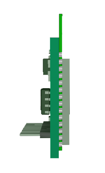
The first issue is the form factor. It need to be even smaller to fit into the smallest H0 trains, and it need a better connector solution. I used 1.27 pitch holes as connectors, but this decoder is generic and need to be soldered on. I can just about do 1.27 pitch, but most people will struggle with this.

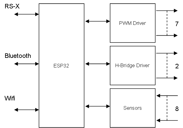
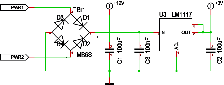
Limiting the design to 12V, no sound, no positioning and no utility functions on main board. I will rather use an extension bus to allow for utilities and sound to be added.

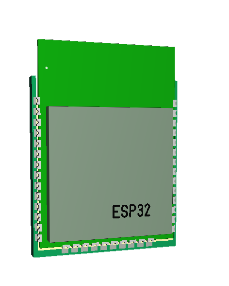
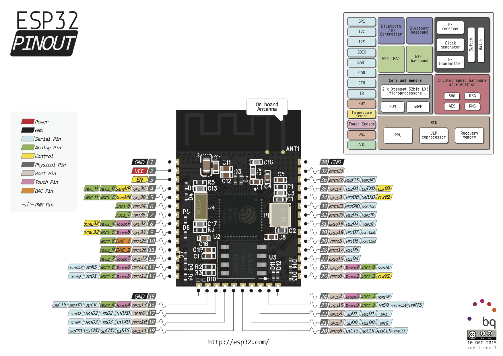
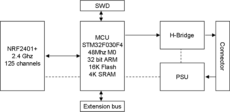
As for MCU I have 3 options. I could go with NRF24L01 and replace ESP-03 using a STM32F030, or I could use ESP12E and control things directly from this. I could also use an 8 bit AVR, but the reason I don’t is because the AVR chips cost 1.50 USD while STM32F030 cost 0.50.- USD. 3.3V also goes better with NRF24L01.

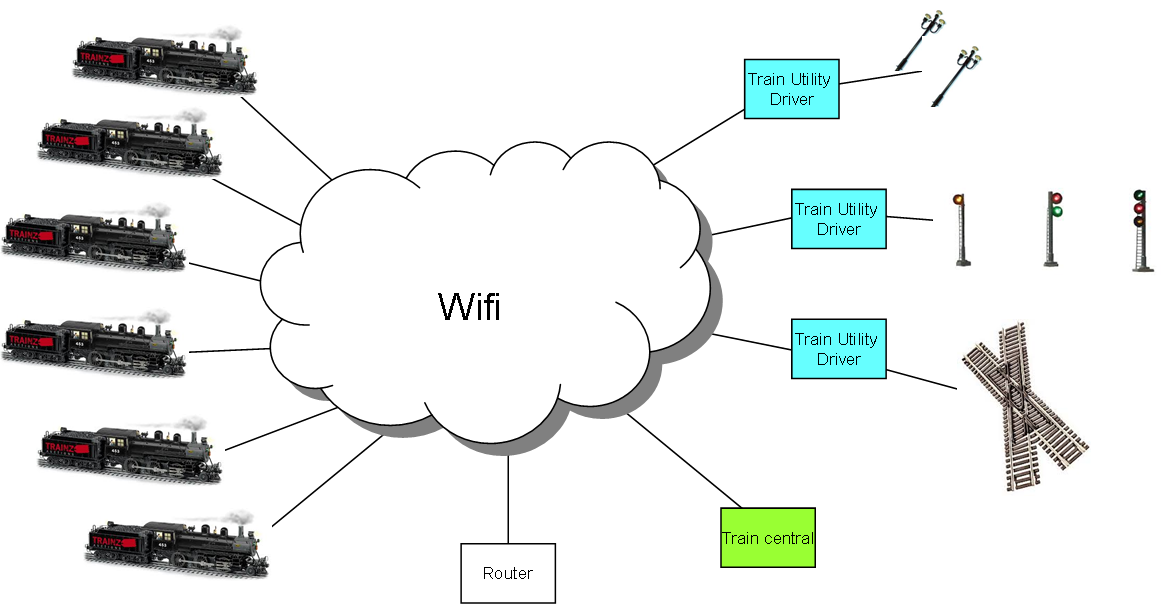
Having Wifi directly requires a router + it is not so great with maybe hundreds of trains running, so I go for the smaller NRF24L01+ breakout bords. Shockburst (NRF24L01) is open, but it is rather easy to create a system that reject non-intended messages.

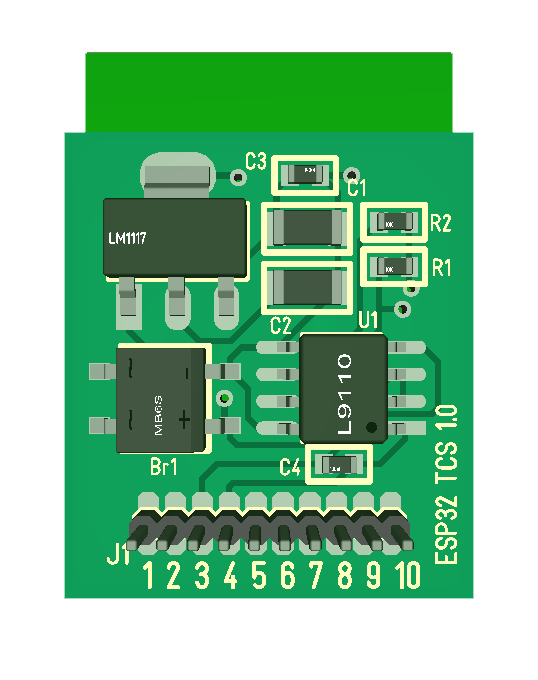
And one last modification – lets replace those 1206 components with 0603 ones. This was my first SMD design and the small size scared me, but these days a 1206 looks like a large dinosourus.