ESP32 with Visual Studio Code & Arduino

Having used Arduino IDE to develope the ESP32 Utility Driver code I must admit that while I in general like Arduino I also miss a proper code editor. Sticking to Arduino (for now) I decided top try out Visual Studio Code.

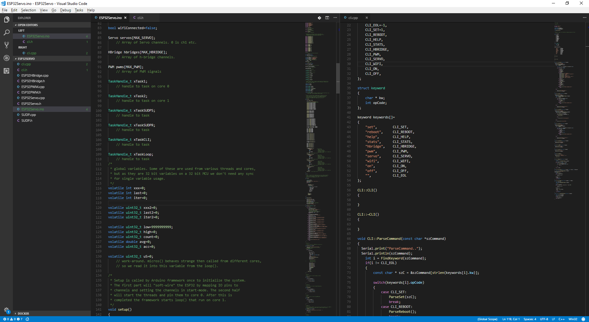
Visual Studio Code is basically a free and liteweight version of Visual Studio. In this case I just opened the folder and voila. This gives me the option to edit code here and use Arduino IDE to compile and upload.

I am fully aware that more advanced options exist, but I intend to stick to Arduino libs on this project because they are straight forward to use. I actually have the full toolchain & ESP-IDF etc installed. This would probably be my own preferred ways of working, but I need something that every hobbyist can work with – no fuzz – with as little fuzz as possible.

It’s other coder alternatives than Visual Studio Code. Friends of mine stick to Emacs etc. I learned years ago that you don’t mess with developers personal choises unless you want them frustrated and less productive. So whatever works for you is fine.

A note on Arduino 1.8.5 is that it will not detect changes made by a different editor, so changes will be reverted if you save from Arduino after having changed a file from another editor.

ESP32, Arduino & FreeRTOS

One of the things that I am not happy with is the FreeRTOS implementation on the Arduino ESP32 library. I try to reserve core 1 for bit-banging and I have a nice average 4uS accuracy. But, I also have 110uS long iterations ca once per second as I activate WiFi. Also, I fail to activate WiFi from anywhere but “loop()” (core 1). Any attempt on doing this from a thread causes FreeRTOS to “panic” and result in a core dump.

I suspect that it either is a FreeRTOS thread or interrupt that uses core 1 and not core 0. 110uS means 10% accuracy on a Servo Pulse. But, more important is that FreeRTOS get’s in my way. This is a classic conflict between hard real-time and threading OS designs.

Threading means that a OS uses a system interrupt to switch jobs. This interrupt can run 1000 or maybe 10,000 times a sec. At 10,000 times a sec I would expect 5-10% CPU load on ESP32 for this alone. The reason I do a round robin loop on core 1 is because I get higher accuracy. But, as Core 1 obviously have other things that slow it down I will need to look into that.

It is not critical for my 12 Servo channels because I also have 16 Led PWM channels available. Simply said I don’t need to bitbang the 12 Servo channels on the ESP32 Utility Driver and H-Bridge and PWM is less sensitive.

A Servo pulse is 50Hz, but last about 2500uS max, so 110uS is between 5-10% accuracy. 10% is sufficient to get me worried that the Servo  might have a minor move – in that case it would look like nervous twiches as the Servo try to hold positions – not sure. But, as I said – I do have the Led PWM’s that comes with a much higher accuracy.

ESP32 – CLI/Simple HMI

While I am working on more permanent HMI solutions I need a CLI that communicate through USB that can initialize the ESP32 based designs. A CLI is a command line interface that act like a brute force interpreter. In theory we could implement a full Unix alike shell, but I only want a few commands that is a must. But, I also recognize that this is a good way of testing board features before the HMI is finished – so here it is;

  •  *    set wifi <ssid> <password>
  •  *        // will set the ssid and password
  •  *        // automatically used at next startup
  •  *
  •  *    reboot
  •  *        // reboot the device
  •  *
  •  *    help
  •  *        // list available commands and syntax
  •  *
  •  *    stats on|off
  •  *        // switch statistics on/off.
  •  *
  •  *    hbridge <ch> <dir> <pwm-duty>
  •  *        // set hbridge to move
  •  *
  •  *    pwm <ch> <duty>
  •  *        // set pwm to duty
  •  *
  •  *    servo <ch> <pos>
  •  *        // set servo pos

For now I will use the Serial port through Arduino IDE. We can add more commands as needed. Later I will need to add this through Wifi/Telnet so I can test Model trains as well.

Adding Wifi to DPS5005

The DPS5005 contains a USB/RS485 interface so both PSU’s can be remotely controlled. I want to use this option to create a Wifi based PSU. ESP-Wroom-32 do have 3 UART’s, so we can still keep UART0 for programming and use UART1 & 2 for each board. I do however notice on the original USB board that the vendor used photo couplers and I think that is a good idea. I would otherwise struggle with ground between the two PSU units that needs to remain isolated from each other.

The only concern here is that the opto coupler’s have limited data rates, but DPS5005 comes pre-programmed with a fixed baudrate anyway. The schematics above is just one I found and modified in Powerpoint of all things. I am not sure ESP32 is capable of driving an opto-coupler directly, so we might need transistors. I obviously also need a separate PSU as I can’t feed from any of the main ones. The signal from DPS5005 include a 5V PSU to feed that side, so we will be using 3 separate PSU’s on this board.

The long walk with HMI Designer

Working with software is often long hours with invisible progress. In this case I worked on the Edit Control. I actually tried to use a standard Windows one, but decided to make my own from scratch. In effect it is only a few things I use from Qt including their interface to OpenGL.

Edit Control – that can’t be much work right? Actually it wasn’t, but it forced some design changes to get it the way I want it. The picture above show inline editing with no borders.

Having coded C++ for years before learning C# and Java I actually want to implement some of the C#/Java techniques in C++. This is about making things simpler and more efficient to code.

One of the issues is Reflection. In C# you can assign an object to the property editor and edit it’s properties. Doing the same in C++ is much simpler than people think – you simply add a linked list declaring your member variables and voila – you can edit, save xml, read xml with a few simple commands.

Another issue is Events. I often need to call a parent class from a sub-class. Again if the sub class simply have a mapping table that I can set from the parent …

These techniques do however dig into the memory and dynamic side of C++. But, it leaves me with what I want – a HMI without C# or Java around to slow it down.

Dual 0-35V/0-5A Variable Lab PSU – Assembled

This shows the assembled PSU. Only one of the DPS5005 modules are mounted as I am still waiting on the 2nd. You can see the driver stage mounted inside. The black painted front turned out quite nice.

This is the back side with the mains connector, fuse and switch. I have to wait a few weeks for the 2nd module, but I am quite happy with this PSU. Actual max voltage out is 34.75V as input is 35.75V. Current limit is +/- 0.005A according to the build in meter.

Dual 0-35V/0-5A Variable Lab PSU

I recently bought a DPS5005 which is a 5A variant of the larger 20A DSP5020 I wrote about earlier. This module can deliver 0-50V/0-5A and have all the electronics inside the display module. Testing of this proves to be very good and it’s a good match for the 36V/5A driver module. As it all also fit well within a low-cost metal cabin I decided to build a dual Lab PSU.

The picture above is the HMI module. The larger DPS5020 have a separate regulator board while the smaller DPS5005 have the regulator board inside this module which makes it very size optional. Both modules are with USB. Basically I just wanted the RX/TX and Modbus in place so I can expland the Lab PSU later.

One of the things I really like with this HMI is that turning the knob by accident changes nothing. You actually have to press A or V first. You also get to adjust out power before setting it out. In fact the HMI does not look like much, but it is very impressive and clever design.

This picture show the 230VAC to 36V/5A driver module available for ca 10.- USD. DPS5005 can deliver 50V out, but as this module is limited to 36V it delivers only 35V out. This is however more than sufficient for basic needs.

This is the 17.- USD box that I use. The plates are steel, so it’s a bit of a job drilling holes etc. But, it is sufficient room for fuses and mains connection, 2 x driver modules, 2 x displays and 2 x PSU connectors. Making the holes went a bit messy. Basically the plate ended up bent around my drill, so I I had to hammer it back out and decided to change color. Was not too found of the blue in the first place.

This shows the all-in-one mains connector, fuse and on/off switch. The only drawback is that I end up with the on/off switch on the back, but I can live with that.

The last component is this female banaa plugs in front, one for each PSU. The table below show the BOM and the ca total cost of the PSU. All these parts are avaiable on www.aliexpress.com

2 DPS5005 32.- USD 64.- USD
2 Drivers 36V/5A 12.- USD 24.- USD
2 Banana connectors 2.- USD 4.- USD
1 Mains connector 4.- USD 4.- USD
1 Cabinet 18.- USD 18.- USD
Total 114.- USD

A single PSU 0-30V/0-5A is usually around 100.- USD with P&P. A dual PSU (cheap) would be ca 150.- USD++. This is a programmable, dual PSU. It will cost me anoth 50.- USD to add the ESP32 and HMI later, but once that is done you have a PSU that normally cost several times more.

ESP32 Servo Programming Example

This little example demonstrate how simple it is to create a Servo using the build in LED PWM. ESP32 comes with 16 channels of PWM, so in setup we asscociate channel 0 with pin 14 and set pin 14 to OUTPUT. We also set channel 0 to 50Hz 16 bit PWM. The example will sweep 0-180 degrees using GPIO14 as signal.

#define SERVO_PIN 14

void setup()
{
   pinMode(SERVO_PIN,OUTPUT);
   ledcSetup(0,50,16);
   ledcAttachPin(SERVO_PIN,0);
}

void loop()
{
   for(int x=0;x<180;x++)
   {
      SetServoPos(x);
      delay(10);
   }
   delay(100);
}

void SetServoPos(float pos)
{
    uint32_t duty = (((pos/180.0)
              *2000)/20000.0*65536.0) + 1634;
         // convert 0-180 degrees to 0-65536

    ledcWrite(0,duty);
        // set channel to pos
}

A servo signal is a 20ms pulse (50Hz) with the signal as a 500uS – 2500uS width to indicate servo angle.

ESP32 Programming with Arduino IDE

ExpressIF implemented FreeRTOS with their Arduino IDE library, so by using this we get a lot for free. By default we run Wifi etc on core 0, while the classic Arduino loop() run’s on core 1. In my case I want to use core 1 for bit banging and that is straight forward to program in loop(). By using an ever loop I bit-bang with < 50yS accuracy which is very good.

The more tricky part is the communication tasks that we have to add to core 0. Firstly we need to deal with the Task Watchdog. Since core 0 is used for system tasks it also monitor it’s tasks and trigger the watchdog if any of them run forever, so we need to (1) create a loop, and (2) call delay within that loop.

The console print below show a loop w/counters in loop being monitored by a task in core 0.

Ca 526191 iteration a second and stats show that we max have 10uS delta with an average of 1.9uS between iterations. This is our bit-bang accuracy. These 10uS will probably be 50uS as we add content, but that is still 50-100Khz accuracy or 0.05 – 0.01ms if you like.

My alternative would be to attempt a 10,000 timer per sec timer interrupt that would give 0.1 ms accuracy and use ca 10% CPU load. I have not tried this on ESP32, but this technique have its advantage that you can use 80-90% of Core2 for something else.

Programming a Servo Controller

It’s time to code up the ESP32 Utility Driver. I am not that found of Arduino IDE, but it works and I like the wire library concept and how it simplify things. A Servo port is a signal that send a 50Hz pulse. The technique I suggest is a bit-banger where we loop as fast as we can checking pulse length. We set up the 12 signals in a table, start them at the same time and then iterate as fast as we can closing them at the proper time to get a correct pulse length.


The alternative is to use an interrupt. This could work, but we would get a resolution of 1ms (1000/sec) or 0.1ms(10000/sec) max. Any interrupt faster than that would use to much CPU time. Another technique would be to bit-bang signal 1, then signal 2 etc. this is what the classic Arduino library does. The technique I suggest gives a much higher resolution as we iterate and check much faster that we can use interrupts.

This would have worked well with a single core, but as we have a dual core we can allocate this task to one core and I expect something like 10uS accuracy or 100Khz sampling if we use this as  data sampler.

We have 21 IO ports to maintain in an iteration:

  • 12 Servo or IO ports
  • 2 (4) H-Bridge signals
  • 7 PWM signals

ESP32 is perfect for this job as we can use 1 core for this purpose while the second core handle the Wifi and easyIPC that I will return to later.