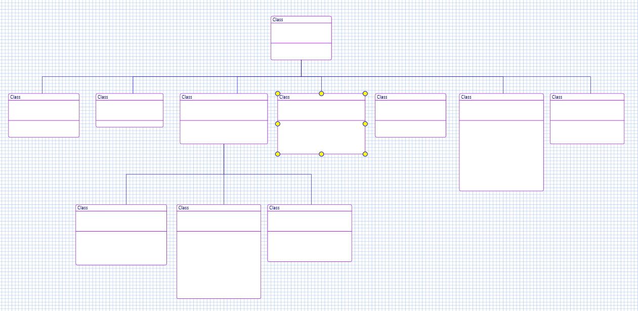
This example lack a few details, but it illustrate the need for a specialized line where we in this case have a common horizontal level. Without this the diagram would be messy. In this case I have a common horizontal line because all symbols are at the same Y position, but I will need to be able to control that. The solution is that these exact lines need a fixed horizontal level rather than just the mid position as used here and I need to be able to manually control the level of that combined line.
You don’t need to draw class diagrams like this with parts of the line common, but it makes it easier to read. This is just a mockup example so i will return to this detail later as I do UML Class Diagrams properly.
I learned Object Orrientation with OMT which is one of the methods used to create UML and class diagrams are IMO the most important diagram in modelling information because a single, quite simple diagram helps you remember better. The more you remember the better the structure and quality of your system becomes. In BSA I will use classes and class diagrams to model data first and foremost, but you will be able to locate functions drawn in PLD to classes as well.
Precentation is a topic I will return to. Physical classes can contain a lot of details that I am not interested in showing on “this” exact diagram, so I need a precentation layer where I can select parts of a model to draw a non-physical diagram for the purpose of illustrating selected functionality.
The most interesting detail in this example is actually the speed of drawing this example – this is done with BSA and it was drawn in a few seconds. If you try this in most available UML tools you will notice that it actually is a bit of work to get this drawn.