I paid 31.- USD for 4x 4 layer PCB’s from JLCPCB and they arrived after 1,5 week. The only drawback is that they do not pay tax directly so DHL had to do that charging me another 30.- USD for Tax and Handling. But, I am very pleased with JLCPCB so far. Below is a picture of the mechanical assemble test I did yesterday.
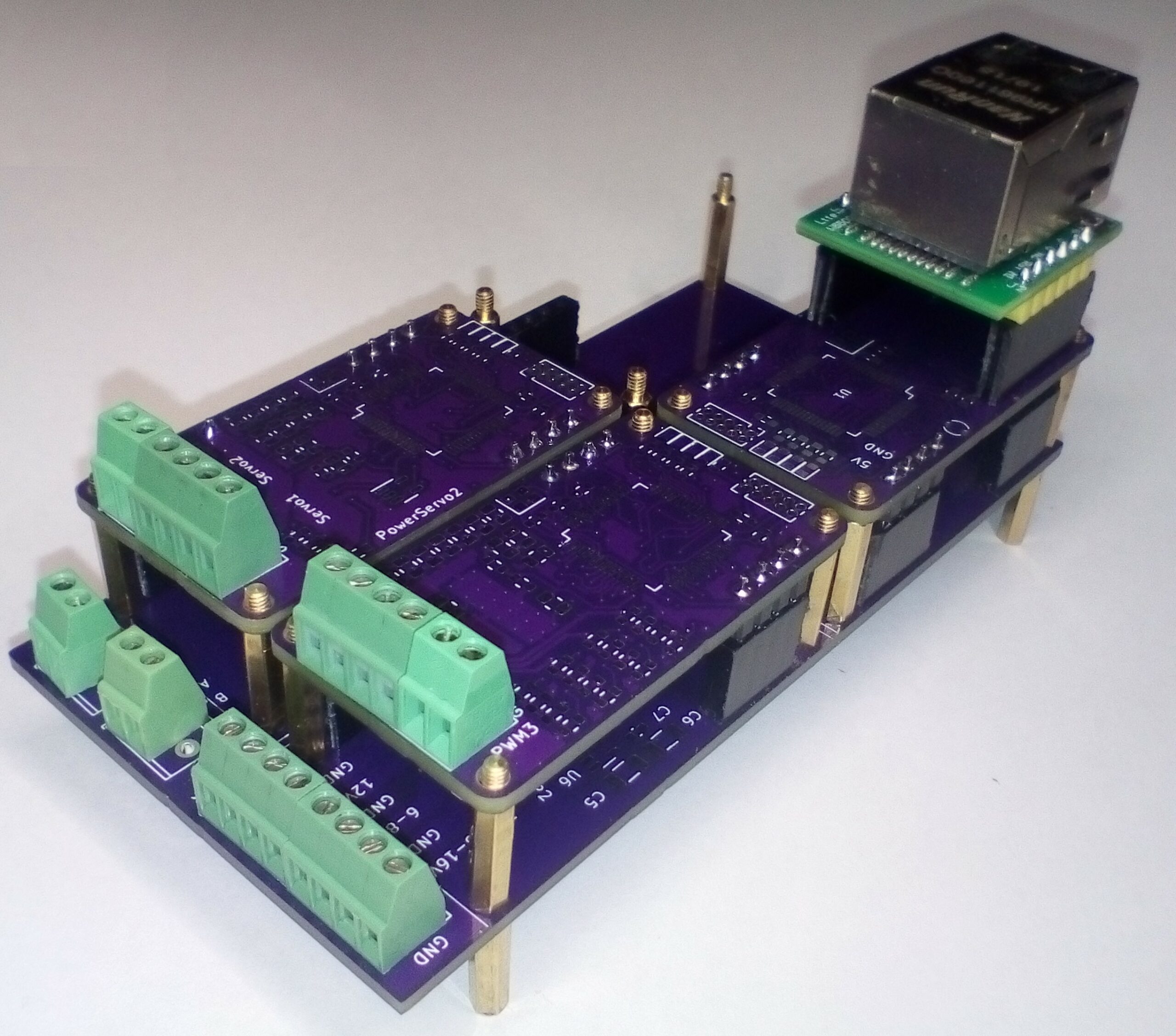
The USB-C on the Ethernet module is to low causing a conflict with the power terminals, so The Ethernet module can only be used on one side. I also discovered a schematic error on the Ethernet module, but other than that this was very much as expected so far. The crystal on the Ethernet module is the wrong footprint and position is to tight for the W5500 header anyway, so I will have to test without this. I have only mounted mechanical components so far and I am very pleased with how the 2.54 pitch headers and modularity worked out. The modules are very easy to mount on the motherboard. This is a very small system. This picture do not give a real impression of how small this actually is, but measure up 25mm x 45mm on a paper and you will see
One of the modules have 80ich components so they will be hard to assemble manually. I am not so impressed with purple color on PCB’s – I will use different colors next time, but the reason I used purple color is becaise I hope to use this on my x-mas tree to blink led strings 🙂
The Ethernet Module becomes a little tower since I used headers for now – I don’t want to waste a module by soldering it directly on yet + I need 2-3 mm clearing anyway so it will be a bit tall. I will make a proper Ethernet module with a low profile RJ45 later.
I do however need to look into production cost on these modules. I mount components on both sides meaning I will need to run two assembly runs and I use five hole through components on each module that require manual soldering – that drives cost, but the worst is STM32G491Rx that cost 12ich USD each. I love STM32, but not at this cost. I have a few options that I want to look into:
- CH32V307Rx is at a different cost base. It does not have CAN-FD, but it do have a Ethernet w/Tranceiver for 10M. I am considering testing out using that as IPC by having the magnets mounted on the motherboard and adding a 4-port Ethernet Switch on the motherboard.
- Another option is to switch to either STM32G0xxxx that also have CAN-FD or downgrade to CAN and use the lower end of CG32V that cost < 1 USD. That will save me ca 10.- USD per module. I can re-use the motherboard as is so I will make test boards for this one.
- I can replace the SWD with a different one that do not require a hole through connector.
- I can use more space to get components on one side only.
For now I just want to enjoy x-mas and mount these. Luckily parts for my PnP has also started to arrive and looking at these modules I must admit I look forward to be using that. It’s been a while since I did my own electronics so this will be fun.