I was recently asked to create a PLC in the form of a cable and the resulted draft is quite awesome. The design size I decided on was 90 mm x 25mm x 25mm. The reason for the 90 mm is tto have a fit for standard PLC boxes. 25 x 25 is a reasonable target. This led me to create a motherboard with 1 x IPC connector and 2 x IO modules
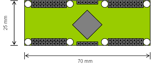
The Motherboard uses 70mm leaving 10mm each end for full height connectors. The total length then become 90 mm as we adapt IO modules. Counting a reasonable pin excanche I settled on a 40 pin 2.54 pitch header supported by screw terminals for now. The connectors are mirrored so that modules can be mounted on either side.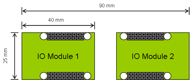
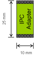
The small 1cm connector in the middle is an IPC adapter allowing me to connect MCU boards together. And this means I can scale as much as I want. I drafted a 2 x 5P x pin header for now. I might add a screw hole. But, I might also mount the IPC directly on the motherboard.
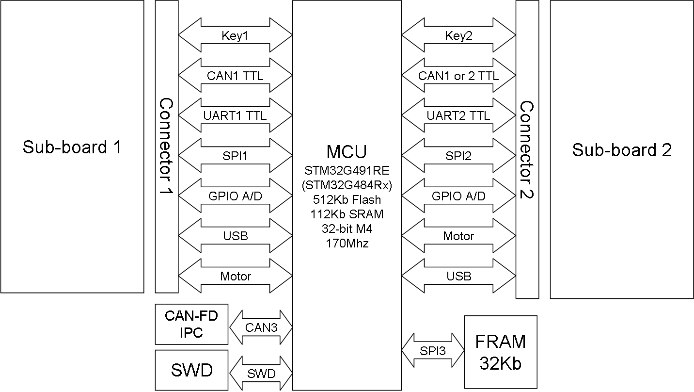
The Block diagram is below. I have already tested pin layout in Cube, but it will be some tricky PCB routing here so I expect 6-8 layers on the MCU board to achieve signal integrity.
As for IO Modules I decided on a few issues that still is on draft leve:
- Connectors are identical and mirrored, so a module can be added on either side.
- Key is X pins that identify the sub-connector. I would like to have this, but I am running out of pins so will have to work on this.
- 1 x CAN-FD TTL on each side. And a 3rd on IPC to interconnect several boards as one solution.
- 1 x UART on each side.
- 1 x SPI on each side.
- I have not considered I2C yet.
- 8 Analogue and/or digital pins – these are common for both sides.
- USB pins connected to each side – not sure if I want to add an optional USB connector on the MCU as well.
- 8 PWM signals supported by a Motor Control Timer.
- I also added an SPI based FRAM w/32Kb for config. This is more elegant than using Internal Flash for config.
IO Modules – the list can be as long as you want:
- Ethernet Adapter.
- Wifi Adapter.
- Disk.
- Display/Keyboard Interface.
- RaspberryPI IO.
- RS232.
- RS485.
- CAN (FD, HS, FT)
- Analogue modules.
- PWM Modules.
- Digital IO modules.
- 3-P Motor
- DC Motor
- Stepper Motor
- Sensors.
- never ending story…
More to come…