This is a 2 x Power Servo module I just made based on the PWM3. The circuit is very similar except I removed the DRV8313 and 3 of the current sensors. Controlling a servo is about sending a pulse at 50Hz between 500uS to 1500uS – and I have some 60Kg Servoes that can drain up to 6.5A – so I kept the 6P connector and made 2 power servo connectors that actually can support the currents needed. I need to add TVS (or opto coupler) on the servo signals and this is done – most of the routing was kept from PWM3.
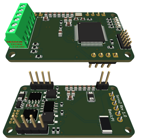
In this draft I have suggested to re-use the 24V pin as 6-8V pin – I will probably modify that because I woudl need jumpers on the motherboard for this and it would be a disaster if I plug in a module on the wrong slot – I kept the capacitor bank from PWM3, but have plenty of space to move that onto. I might even consider opto-couplers on signals on this one.
Current usage on a RDS5160 is rated to 3,5A on 6V and 6,2 at 8.4V – I have ca 10A in total on this module and those header pins will support ca 16A – it is the PCB lanes that limit the currents. But, it is a current sensor on all the power consumers because the real budget will be what the motherboard supports.
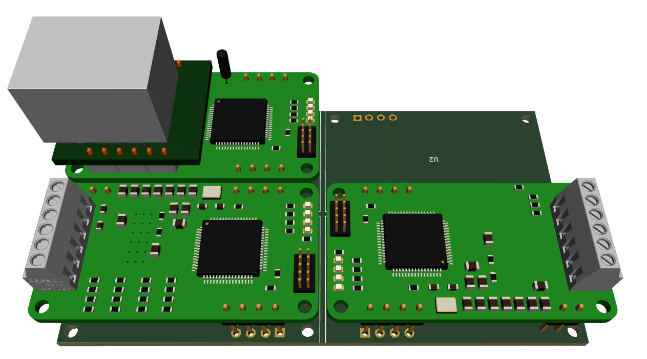
Three different modules mounted above – I need to finish the motherboard and the real modules have some text, but looking at PWM3 and teh PowerServo it would be easy to do a mistake – so I will stick to the plan of separate pins for different voltages.