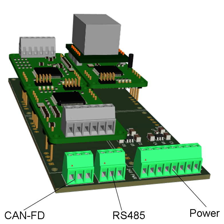
I have done several experimental modular control systems that was scalable, small in size and based on MCU’s. My first experiment was with Basic PI Hats and I later did a smaller, modular system illustrated below. The system below was actually a great success. Specially the keyed connectors worked well. What did not work so well was the size, components on both sides, mixture of CAN/RS485, lack of galvanic isolation and lack of waterproof design. Using this on a mobile vehicle proved to be a challenge as I needed to create a larger, waterproof box around the cards. It become clear that I needed to address these issues and modify the system a bit.
The first change was to avoid duplication of CAN/RS485.
The second change was to replace LQFP64 with LQFP48 on MCU for the smallest modules.
The third change was full galvanic issolation on everything.
The fourth change was waterproof connectors and waterproof box design. Rather than using a random box I create my own.
The fifth change was to avoid two PCB’s on top of each other to get a lower design and avoid extra PCB assembly cost.
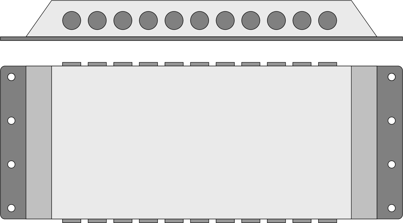
The result is still work in progress, but it is a flat, small, modular, waterproof control system that I can just mount directly on any vehicle and connect with plug & play cabling. The project boxes will vary and the Powerpoint illustration below is only a concept draft. The box is flat with connectors on two sides and mounting brackets on the others. Boxes can be designed to fit content – number of modules. The idea is that you have minimum wiring and only use communication & power until you are close to the actuator/sensor.
I divide units into two categories : CCU (Central Control Unit) and ECU (Electronic Control Unit). CCU is basically the core of a system, while ECU interface actuators and sensors.
My main challenge so far has been to decide on size, design and connectors. The module below illustrate the challenge:
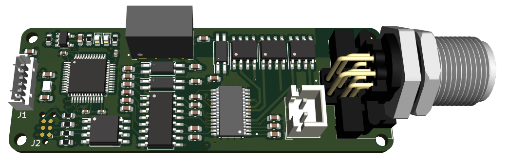
This example module is 25 x 70mm in size and contains MCU, PWM channels, full galvanic isolation and waterproof connector so it can be connected directly to the panel wall. As you can see space is an issue. In my previous experiment I put components on both sides, but I decided to use only one side this time. One argument is lower assembly cost, but more important is the cooling system that the modules mount on to.
Someone will also notice that I have replaced the SWD connector I have used for years with a minimum TC2030 connector (left bottom corner J2). The cable cost ca 50.- USD, but as you have no component on the PCB it saves cost. I have seen these in use, but I have no previous experience with them myself yet.