As I can’t get hold of the components I want and this becomes a prototype that will change I can as well start using both sides of the board. The SOP8 CAN tranceiver get a bit squeezed on the top layer so I can put it at bottom – in which case I can add an optional RS485 as well as a TTL UART because I have plenty of spare IO here. The advantage is that this makes this little board a stand-alone Ethernet, CAN to RS485 converter as well. This boards will need 4.5V to 5.5V input so I need an adapter with a 5V. BOM cost here is an issue, but I don’t want to dig to much into that on this prototype. The usage of both top- and bottom- side will in this case forece a minimum of 4 layers because we need to separate MCU signals and Tranceiver signals as they will be back to back.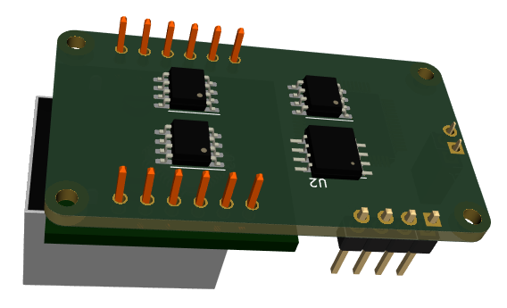
In the example above I have added RS485 Tranceiver, CAN Tranceiver, 2-pin RS485 port, SPI FRAM and SPI Flash on the backside of the module. Adding a 2Mbyte SPI-Flash is something I need to consider because that might be needed for downloading new firmware from remote connection. The issue is that FW will by typically 64-124Kb and needs to be temporarely stored somewhere. FRAM on the other hand is handy for configuration parameters. I am however getting into a bit of trouble because I have more components that needs to be here and is running out of space fast.
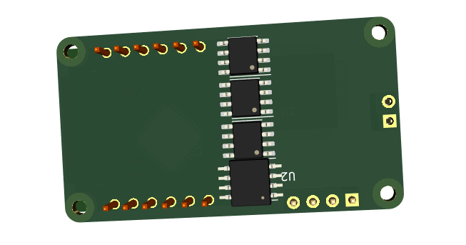
Alternative positioning to optimize space. I will return to these once I have placed the mandatory components. But, as you can see we really could need SO-23 versions of these components. As for SPI Flash and FW download it is nothing preventing us from adding a disc module separately – a “disk” composed a larger Flash.