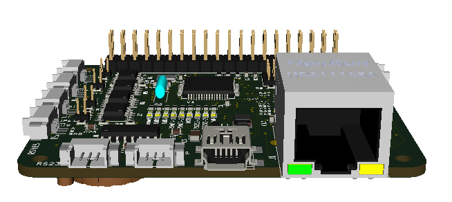
I have a version of XPortHub that works fine, so I have not been in any hurry to make this 2. unit with Ethernet, but I will finally order the PCB’s. XPortHub is very simple as it is only a switch between USB, CAN, RS485, RS232 and Ethernet. But, that exact functionality is what I use the most. The only thing I would change on this is the Ethernet connector as I want to switch to a low profile unit that is lower, but also partly below the PCB to make it easier to put this into a stack.
Just to remiond everyone – all these card are in Raspberry PI Hat format, but they are not depending on Raspberry PI. The backbone in mostly 5V Supply, CAN, SPI (DeviceBus) allowing the cards to be clicked together as a system. Behind the J45 connector is also a Flash SPI and TTL UART connection and the the PCB backside is the battery for the RTC.
- DeviceBus/Raspberry PI Backbone bus allowing multiple cards to be used together.
- 2 x CAN HS ports
- 2 x RS485 ports
- 2 x RS232 ports
- 1 x USB port. Unit can be powered through USB.
- 1 x Ethernet port.
- 1 x TTL UART port.
- SPI Flash.
- RTC w/x-tal & battery.
I have made ca 12 different Raspberry PI Hat designs that I will start upgrading and adding some new designs. The STM32F405RG ticking at 168Mhz w/1Mb Flash and 192Kb SRAM is very powerfully. And the LQFP64 package is just right for these boards. What they need however is an upgrade and more Software.
More important is that I will start interconnecing these with BSA, meaning I get GUI and config utilities as well as the capability to design logic that executes on XPortHub from BSA.
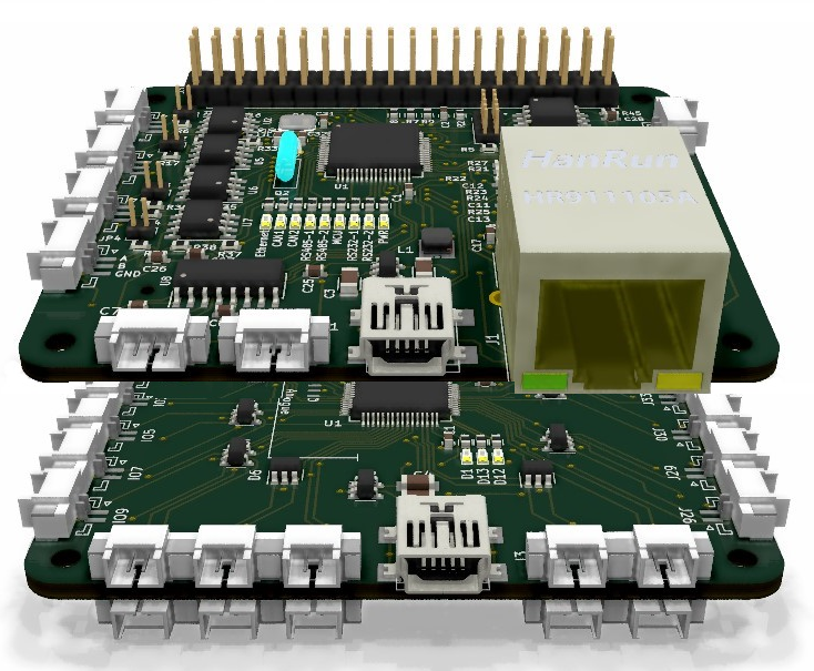
This mock-up shows XPortHub together with a 32xIO board. Each IO pin have it’s own connector with signal/ground. This can be used for multiple purposes as all pins are both input and output and have a decebt TVS protection. More important it has the same DeviceBus/Raspberry PI Backbone so it can be stacked. This is a dead simple, but yet powerfully board.
DeviceBus consist of 5V, 1 x CAN, 1 x SPI and 3 x IO pins. SPI can be used in full or half duplex mode. In Half duplex mode the SPI bus can act as a TDM allowing any device to send. SPI is much higher speed than CAN, while CAN arbitration means any board can transmit. This is easier for start-up config etc. And tbh CAN is sufficient for most needs. Sadly RPI can’t communicate on CAN, only on SPI. But SPI is perfect for larger data amounts and higher bandwidth. These are so far the only boards that have the full DeviceNET added.
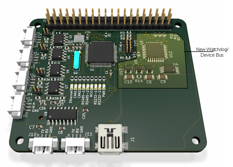
This 3rd board is a test board where I consider adding a 2nd MCU as Watchdog with capability to switch on/off the main MCU. I used a XPortHub, ripped off the right side and added the new functionality. I have to go through the articles and concept, but I will order the board for fun. Part of the idea her is that the 2nd MCU also focus on high speed SPI using a high speed, full duplex UART for the main MCU. This will allow the main MCU to avoid the challenge of high speed SPI bus, but it add space and complexity. My opinion is that it is a bit of over-design, but well – lets order the PCB – fun for dark & dingy days in authumn 🙂 – it is an experiment.