I got the first link designs connecting symbols working. I will not use much time on State Diagrams in first round as my objective is still to create GUI designer first. But, working on advanced, embedded solutions every day I am actually looking forward to be working with BSA once it becomes fully functional. The difference is that in a normal developement you need to attend to all the nitty, gritty code details on multiple devices yourself – while in BSA you specify a specification that is auto-generated into code. In other words you change mind-set from HOW to do things into WHAT you do.
The primary work now is getting the graphic engine working. I am very happy that I switched from QML to WPF. That said – I actually liked QML, just not the hours it took to make something. But, I work in QML as well so getting a GUI designer that support Qt/QML , WPF and Embedded are my first targets. To be realistic we will see the end of July before the first functional version is in Beta . it is a bit left to do + I struggle to find time working on this these days – that is real life for you.
It is going to be a few try and fail on concepts as we go forward. Making a graphical programming tool like BSA is not straight forward. The reasons no-one have properly succeeded yet is because (1) few users give expensive tools that is not available for most, (2) graphical drawings are slower to work with than you expect.
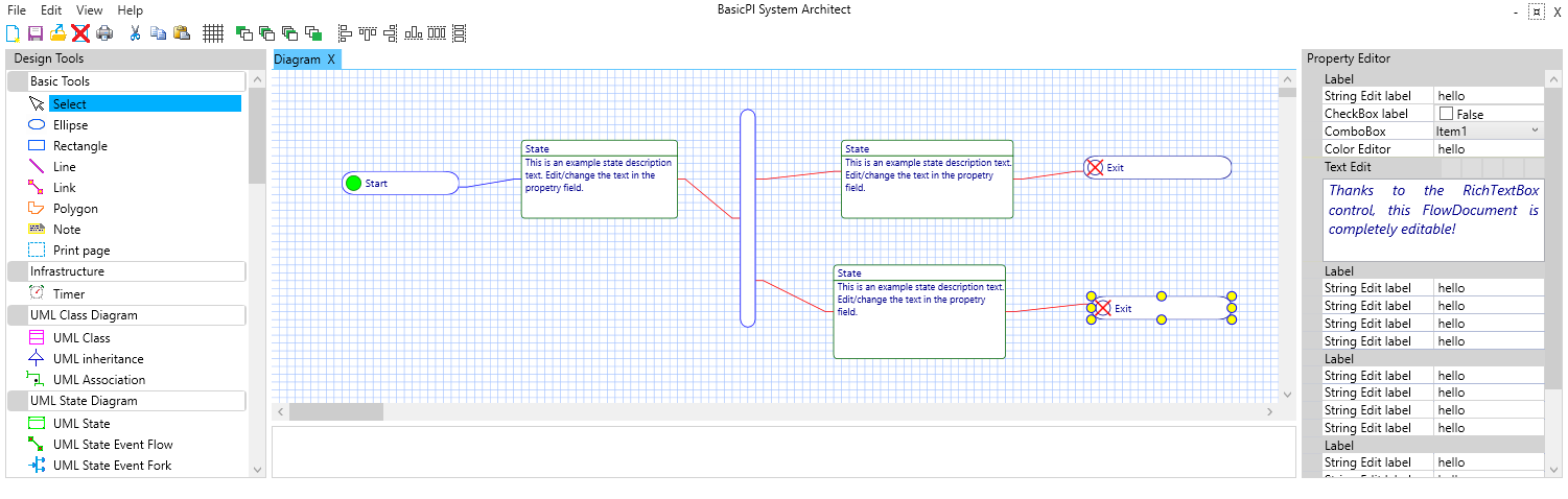
Looking at the diagram above you actually see one of the challenges – details needed for executable accuracy is hidden. The is partly deliberate to force you into a WHAT mode, but it is in your way then you want to check logic. The option is that you need to click on each symbol to check details – which is a clumbsy way of reading source code – so I need to work a bit on this one – how to increase visibility of nitty, gritty details then you need them.
All this has to do with one single objective – speed of development. Having diagrams is somthing I do regardless to have better overview of larger projects. used correctly they do a lot to the quality of your projects. Having them a way of coding should significantly increase your coding speed – but, you need to be aware that specifying logic on a graphical editor is much slower than on a simple text editor if you do it 1:1 – this is why BSA must be an extension to ordinary programming platforms like C#/WPF and Qt/QML – not a replacement. I still intend to write building blocks for BSA in C++, C# or whatever. BSA should deal with WHAT you do and leave it to clever programmers to make the HOW logic in whatever they need.
As mentioned a few times – BSA focus on distributed systems. In this example we could easily be sending a signal flow between computers coding one block on STM32 and another on a PC in the same diagram. This abstraction is something that is easy to do with a UML state diagram as show above.
I have tweaked the standard UML State Diagram symbols a little. Mostly the terminals that I decided to merge UML State Diagrams with what I planned for PLD. But, it is still a UML State Diagram. You have to expect a few tyweks like that as some parts of the model standards need to be adapted to executable accuracy.
The terminals are input/output signals with parameters. The diagram itself become a building block you can use in the next diagram etc.