UML State Diagram is a standard, but I find it’s implementation into tools to be wage. So, I implement my own adaption because I intend to have a 1:1 with actual source code. This is not uncommon as most automation tools will have to make adaption in areas where executable accuracy is weak.
I was introduced to programming with UML State Diagrams through a different tool that I found to be of little use. But, it demonstrated the concept and I often use state diagrams so why not have one that actually is 1:1 with code on high level. A state diagram lack a lot of executable accuracy as it is only a high level diagram, but it does have some excellent qualities of showing event/signal driven flow on high level and as such accelerate overview of source code. The examples below are preliminary from an experimental tool.
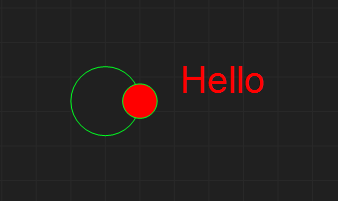
The first symbol I use is the Entry point – a simple circle with a single output connection point (the red dot). All events inthese examples have the name “Hello”. The Red dot indicate that this diagram is illegal as a mandatory event is not connected.
This adds the Exit symbol and an event-flow between them showing a minimum, legal diagram. To draw this you first select the Entry/Exit symbols adding them, secondly you select Event Flow and draw a line between the 2 red dots. The dots dissapear as the events are connected. An output must connect to an Input etc.
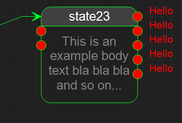
The next is the State symbol itself. As you select a state you can chose between a generic sub-diagram, block of C++ code or premade component. All state’s will have a list of input and output events that at start will be displayed as Red or Green dots. Red dots represent abstract events that must be connected, while green dots represent virtual events that you can chose not to implement. Virtial events can also be hidden (tagged as ignored).
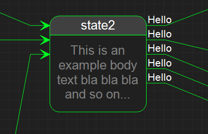
The dots will be replaced with lines and normal text as events are connected. The text “This is an example body..” will reflect the actual content – or by your choise a free text. The standard actually have a entry/exit notation – and I will need to do some adaptions on that.
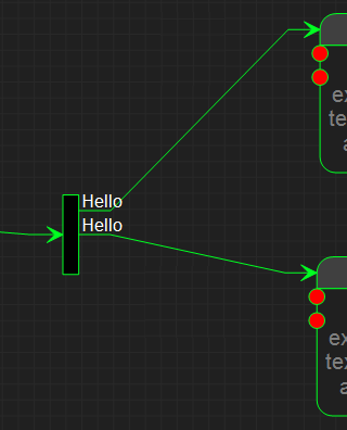
This is a Fork where an event is duplicated and sent in parallell to two different states.
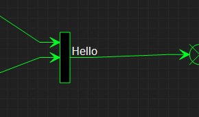
The opposite of a Fork is a Join that syncronize events.
As mentioned – this is an experiment, so I need to adapt as I go to develop the tool. The technique is not as mature as PLD and I am not sure about it’s actual worth, but I like the concept and want to see if this way of coding actually add value then done right and in combination with other techniques.
The tool itself needs a bit of work before its usable for anything and its an experiment as I complete the graphical editor that will be used for PLD as well.
