It is now ca 2 year since I started this blog writing about a Model Train Control System. The system had several newbie issues, but what stalled me was the 40Khz sender I needed for the position system. I never found components with correct size and cost that could do the job. The design itself also had issues. It was to wide, H-Bridge was wrong and mounting the MCU on one side and ESP-03 on the other side created a lot of unexpected interference heat.
Moving on I would like to simpify the design and complete it. I need to return to the position system because I have no working solution for this. It is not only about solving it, but doing it with size and cost in mind.
The first issue is the form factor. It need to be even smaller to fit into the smallest H0 trains, and it need a better connector solution. I used 1.27 pitch holes as connectors, but this decoder is generic and need to be soldered on. I can just about do 1.27 pitch, but most people will struggle with this.
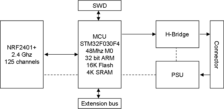
Limiting the design to 12V, no sound, no positioning and no utility functions on main board. I will rather use an extension bus to allow for utilities and sound to be added.
As for MCU I have 3 options. I could go with NRF24L01 and replace ESP-03 using a STM32F030, or I could use ESP12E and control things directly from this. I could also use an 8 bit AVR, but the reason I don’t is because the AVR chips cost 1.50 USD while STM32F030 cost 0.50.- USD. 3.3V also goes better with NRF24L01.
Having Wifi directly requires a router + it is not so great with maybe hundreds of trains running, so I go for the smaller NRF24L01+ breakout bords. Shockburst (NRF24L01) is open, but it is rather easy to create a system that reject non-intended messages.
And one last modification – lets replace those 1206 components with 0603 ones. This was my first SMD design and the small size scared me, but these days a 1206 looks like a large dinosourus.
