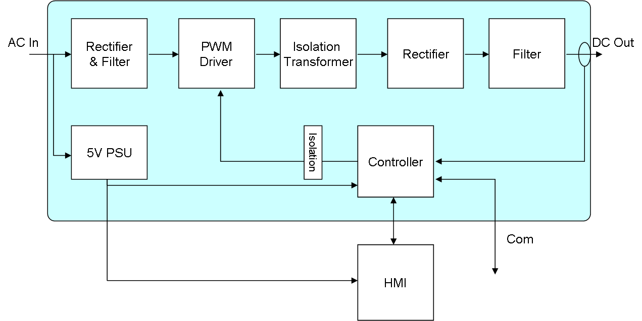
Starting at left with 230VAC input we need a classic rectifier and filter that will produce high voltage DC out. This is input to a PWM driver that will use HEXFET’s to generate a MCU controlled PWM into the isolation transformer. The duty of the PWM decides the output voltage. If we have 400VDC and a duty cycle of 10% we will have 40VDC in average out. The 2nd rectifier ensure we got all positive voltage out and the end Filter (illustrated below) convert this to a stable DC out. To Control this we use fast ADC’s to read output voltage and current into the MCU that control PWM duty.
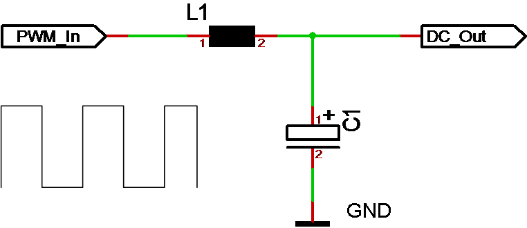
The core of any PWM driven PSU is the prinsiple that we provide a PWM in where an output filter consisting of a coil and capacitor force this back to a stable DC. Voltage out is a simple average calculation, meaning that we control voltage with setting PWM duty.