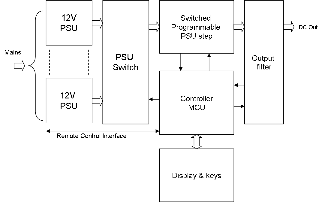
This is just a draft to play around with ideas. I can use standard switched 12V PSU’s to connect to mains. These cost around 10-20.- USD each for 12V/20A. A programmable switch board can connect these to either deliver higher input voltage or more ampere. I would like to target 48V/20A out – but lets see what we can achieve here. The driver we illustrated earlier in the motor controller can become a Switched Programmable PSU step controlled by a MCU and with a proper output filter stage. With a MCU it is also easy to add a display and a few keys as well as a remote control interface for test automation.
The usage of pre-made PSU’s for mains have to do with CE/FCC approval on equipment connected to mains – we can make these as well, but I don’t want to at this stage – maybe later.
Going back to my robot I replace the mains step with a battery and ditch the display etc. As I plan this to be small PCB it can also be a module we plug into our lab PSU and we might have a lab PSU with multiple channels out.
As for the lab PSU we can also implement a real-time oscilloscope on the display showing output current and voltage – with a log window this will enable us to see what we put in and how the equipment we supply behave. I need to think about this one a little + I need to test my theories on output filter, but this start to sound like a fun Project – A lab PSU With these capabilities cost far more than I can afford.