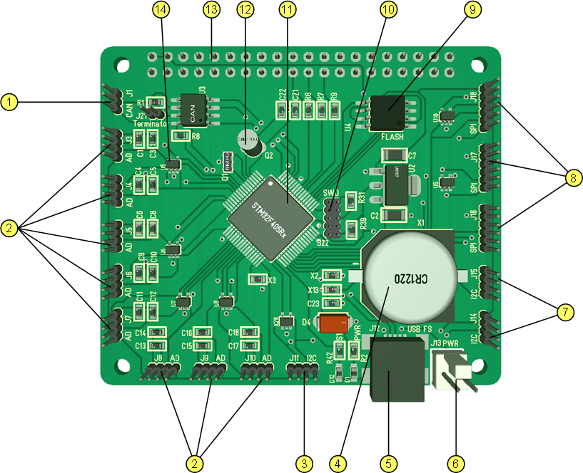
This is a 3D of my Sensor IO Hat Rev 1.0 that allow interfacing to 8 x Analogue/Digital sensors, 3 x I2C and 3 x SPI. STM32F405 have 16 x 12 bit ADC channels and each AD port have 2 IO pins that can be used . The Sensor IO Hat is about connecting to sensors as it have no sensors of it’s own. The only extras here is the Flash and RTC.
- Standard CAN port.
- 8 x AD port consisting of 2 x Analogue/Digital Input/Output each allowing up to 16 analogue or digital sensors in total.
- I2C port
- Battery adaptor for RTC.
- Leds
- USB port
- 2 x I2C ports
- 3 x SPI ports with separate CS each.
- SPI Flash
- New SWD Connector.
- STM32F405RG
- RTC Oscillator
- Raspberry PI connector.
- TVS diodes giving a minimum of pulse protection to IO lines.
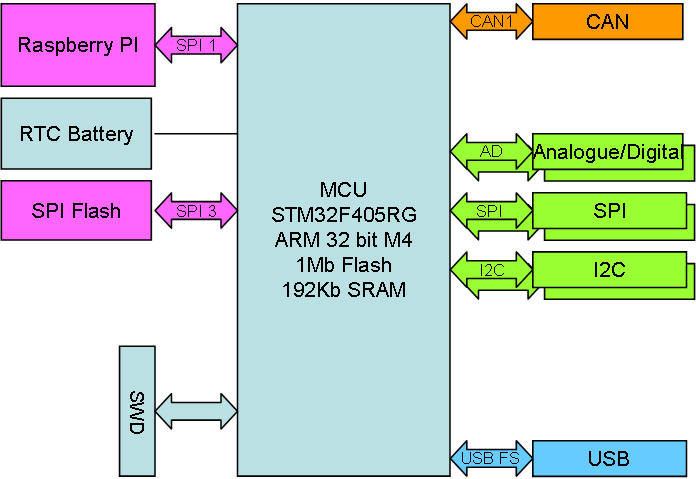 The block diagrams of these Hat’s are almost identical with exception of IO features and that is deliberately to make SW development easier.
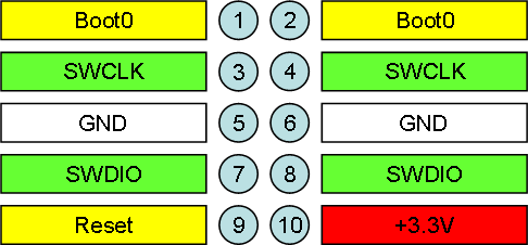
The “New” SWD is based on 2×5 pin 1.27 pitch header and I removed the 5V and UART from the previous version. I tried a 6 pin using JST Micro but found them hard to mount on/off + I had some trouble with the added signal length. This design show here have however worked well and the 2×5 pins are easy to get. Even more important is that using a special male adapter I can program the board without soldering the connector at all.
All SWD connectors will be changed to this format and face in a direction making it easy to plug them in even if a board is in the middle of a stack. For now I still operate without a bootloader, but later I will only program the bootloader and use a USB + SPI to program Boards.