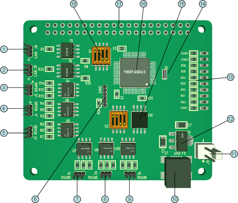
First 3D draft of the RS485 Hub. I have moved all connectors to left and top because it will be attractive to use this together with RPI 3B+ that have Ethernet/USB at right. As mentioned I could have used XPortHub for this, but I often need exactly RS485/Ethernet in higher density because RS485 is very attractive connecting to small, remote sensors/actuators. The drawback With what I do here is lack of galvanic isolation, but I will add a separate Hat for that purpose later. In an ideal world we would add galvanic isolation everywhere, but it comes at a huge size and performance cost (slower Serials), so it makes more sense to add isolation between nodes or then connecting to long wires or special Equipment.
- CAN Port 1
- CAN Port 2
- RS485 port 1
- RS485 port 2
- RS485 port 3
- SWD port
- RS485 port 4
- RS485 port 5
- RS485 port 6
- USB port
- Power Connector 5 external Power.
- 3.3V PSU
- Status Led’s – I admit I went a bit over the top here With 1 status for each RS485 and CAN.
- 8 or 16Mhz Murata x-tal with capacitors.
- Serial Flash. I just added this because I had a spare SPI port.
- MCU
- RPI Connector. I basically use 5V and SPI pins on this Connector.
- Terminator jumper
The actual board will probably change a bit. I like doing these mock-up’s placing connectors and components, but as I start routing I also end up changing things to adapt. Schematics is done, so it will take me a few mornings to get routing done. I find PCB routing to be a relaxing mind game – so yes – this is my form for relaxing.
You probably feel the site have slowed down a bit, and yes it has. To much happening Real Life at the moment so it will be a bit like this for a while. It is also a consequence of me digging deeper into SW as I have an large backlog of things I need to code up.