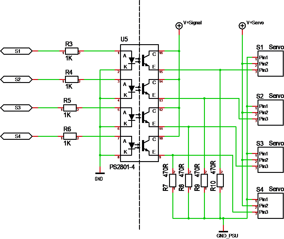
I don’t show to much schematics in here simply because it’s a bit difficult to copy them into here, but had to show this – this is the first time I use a photocoupler. I decided to try PS2801 after realising that a long range of photocouplers use the same package. I am not sure about the resistor values as examples/references are a bit weak. The drawback with using photo couplers is that signal can only go one way and at a frequency of max 10KHz ++. The advantage is that the MCU is totally isolated.
Max voltage C->E is 40V, so if this works as I expect I input a 3.3V signal and get a 5V,12V or 24V out at 50mA. Just need to add jumopers allowing selection of separate Signal and Servo voltage. I will be using 4 of these circuits on the Servo Module.
Sadly this means I can’t use this module for input – I might have to add a separate digital input module – but, I will also look for more optional solutions – learning in progress 🙂