PLC – Ethernet Module

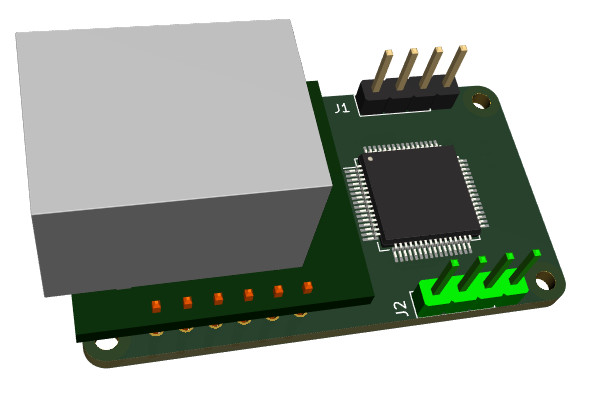
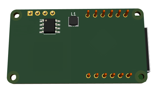
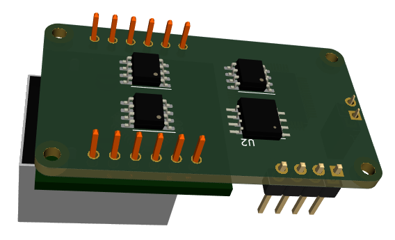
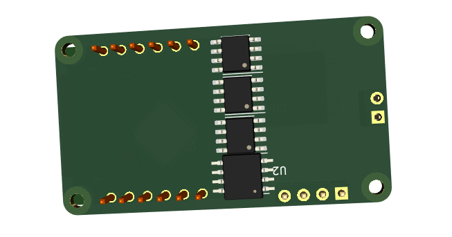
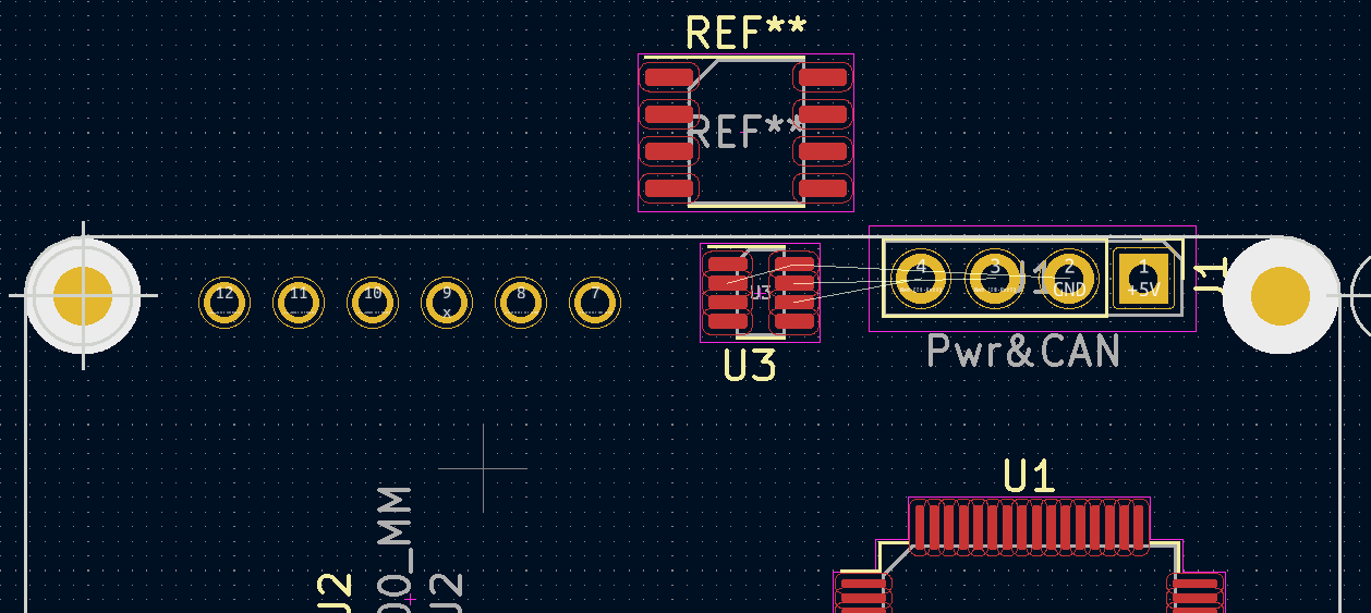
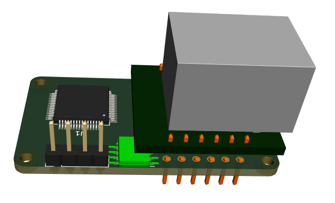
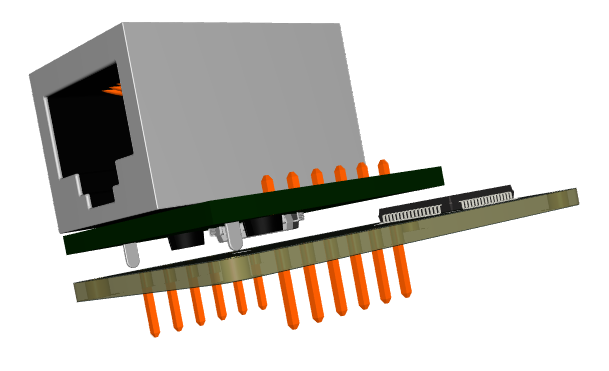
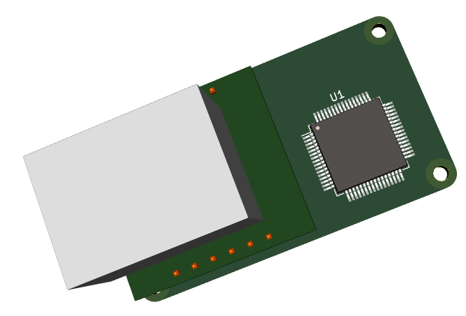
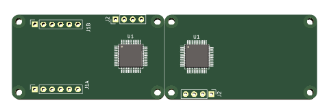
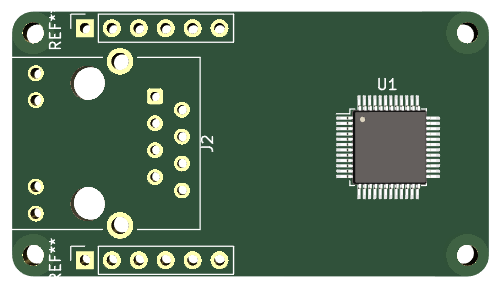
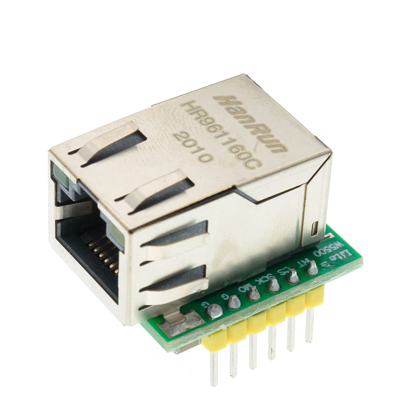
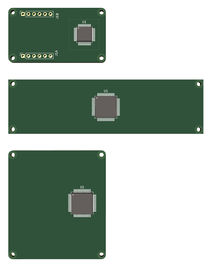
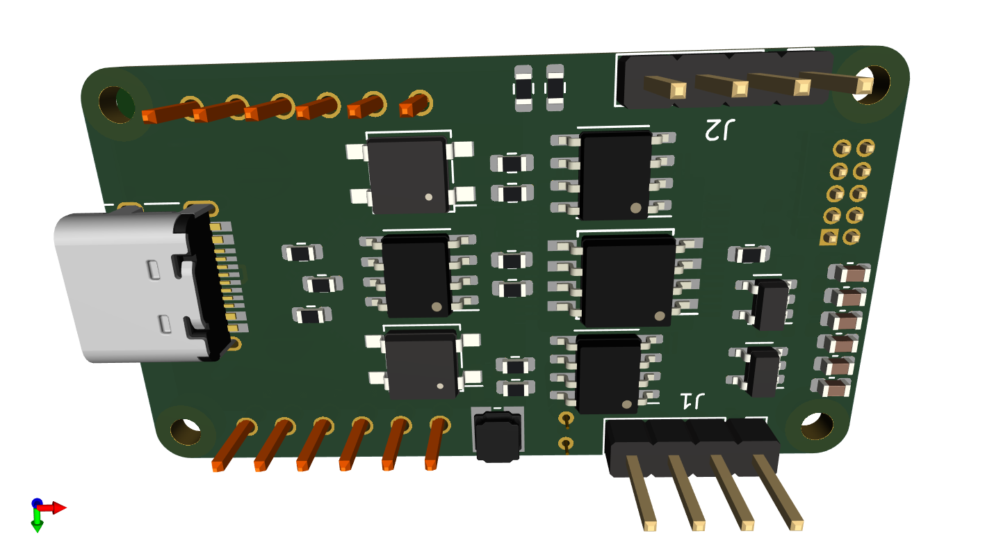
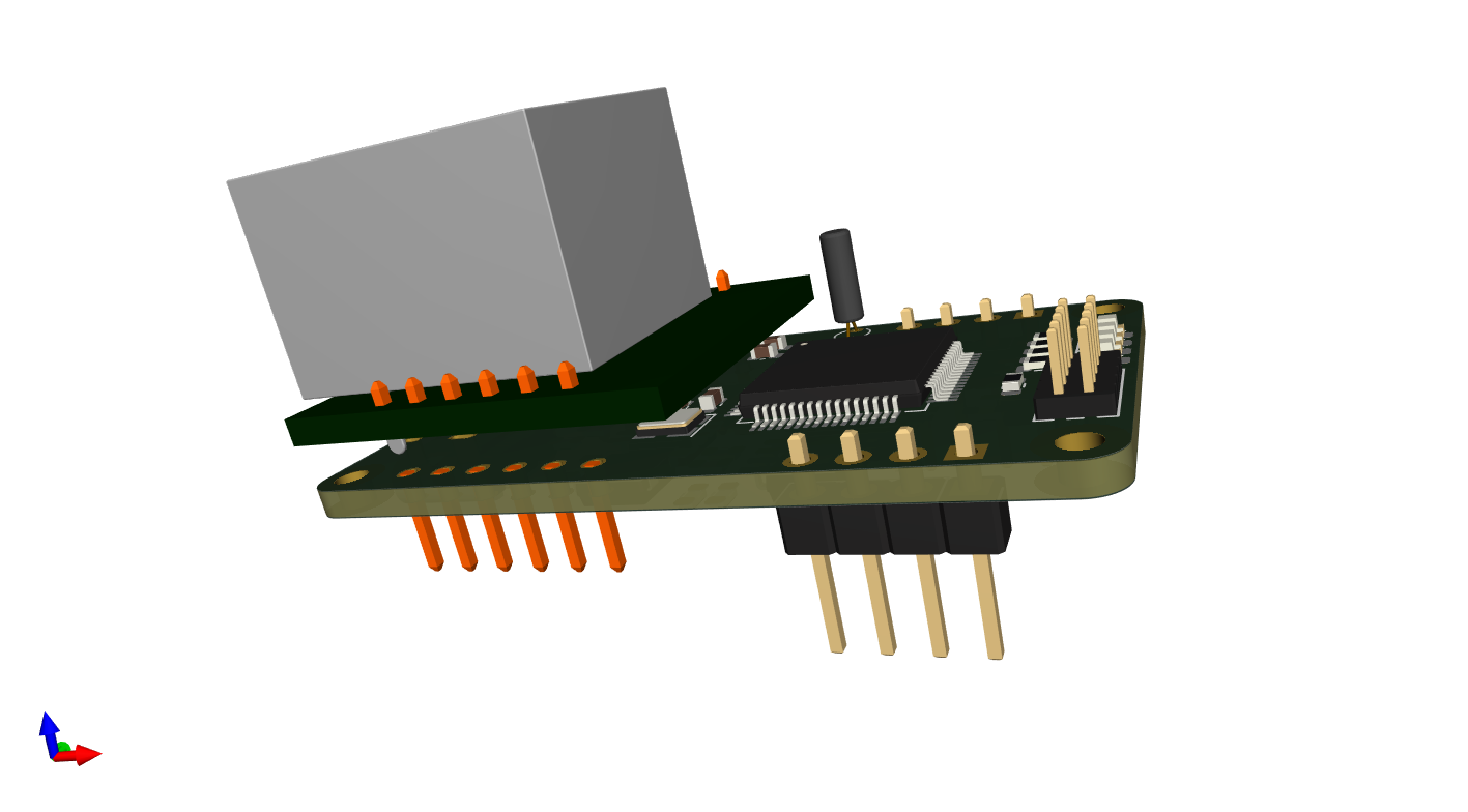
I have finished schematics, footprints, 3D models and placed the components and this starts to look good. The pictures below are exported directly from KiCAD. The Top layer contains the Ethernet module, MCU, crystals, leds and SWD. Only the 16Mhz crystal and some caps are under the Ethernet module. The bottom contains a USB-C connector, a CAN-FD Tranceiver, a RS485 Tranceiver, SPI Flash, SPI FRAM, 2 x SSR 120Ohm Terminal switches and 2 x separate PSU’s that connect if the coil is connected – one for the Ethernet module and one for the rest.

J1 is CAN-FD while J2 is RS485 connected to the motherboard allowing modules using both CAN-FD and/or RS485 to interconnect.  I have yet to route this board and that will take me a few days, but I look forward to routing with 4 layers. As for ordering PCB’s – I get this ordered from JLCPCB and delivered in ca 10 days for ca 20.- USD – not bad. The BOM is 48 components so it is denser than it looks as it is only 25 x 45 mm. I excpect I might have to shrink the board to 24 x 44 mm, but I will return for that.


KiCAD 6.0.8 is great to work with containing many good improvements, but the library is in a bit of a mess loosing old footprints and 3D models. But, well – it is nice to be able to fetch components on the net and import them. STEP models can be found anywhere. For my usage KiCAD is great!

I am still using a few hole-though components because I want to use up my stock + I expect I have to do a few rounds on this. But, a bit of advice – hole through have to be assembled manually so they cost extra. The old fasioned 32Khz oscillator is okich here, but needs to be replaced – I have to think about headers. I want to replace SWD header with a PCB footprint that is excellent. But, well – that’s for later concerns.

In the early draft I considered using a TF Card, but I discovered that this MCU don’t support that. I did also reject the idea of multiple CAN ports and back to back connections and added a RS485 and a 3nd IPC alternative simply because that opens the option to use a long range of MCU’s. UART’s are available on all MCU’s.

I also added USB-C for the first time. It was only a few hours work to find a connector I could soldier and understanding what is what. The part I am most proud of is however the SW controlled 120Ohm termination on both CAN-FD and RS485. I actually fidured this out myself and got a reference design from a more experienced friend showing that I was on the right track. All in all this is actually a very dense, nice design.

PLC – Module Design

I decided to add place for bothy CAN-FD and RS485 as IPC on the module. The design seen from left is CAN at top, RS485 on bottom – switching the module to right we get the oposite. I have the extra space to do it and it allows me to build modules using UART’s only. One of the modules – like this ethernet module can act as gateway between Ether, CAN and RS485.

I have in addition added a SPI Flash 8Mb and SPI FRAM (32Kb) and if I have pins and space I will add USB and/or USART TTL. I did consider TF-Card until I realized that STM32G491 don’t have a HW IO for that. USB is great for just connecting to a PC and download FW using ST’s build in bootloader.

PLC – Ethernet Module Backside

This ends up as a prototype anyway because I lack components to optimize for production. I am using 4 layers this time because I want better isolation between signals. I can mosly route on a single layer, but I had some bad experience with signal integrity on 2 layers. This is the first time I use more than 2 layers and the cost increases quite a bit as well.

I have plenty of spare pins since I used a 64 pin MCU so I will be adding some extras on the back – I am even considering a SD card – lets see -it don’t cost anything to add PCB layout and I don’t have to mount it – this could be a very interesting module at the end.

One drawback is that the mini module cover the screw holes. This will make it difficult to fix this to the motherboard with the W5500 module soldered on, but it is doable.


KiCAD 6.0.8

KiCAD 6.0.8 is great. Many new improvements. But, also some issues as links to footprints and 3D images are broken. I opened XPortHub2 because I neeeded reference to a coil and found that the RJ45 is missing on the 3D View – easy to fix, but I have seen a few of these. You also see some caps and resistors missing etc. Luckily the components I was looking for is here.

Another interesting thing here is that this RJ45 and the W5500 circuit would actually fit on a 25mm x 45mm module if I put the MCU on the other side – just about.

KiCAD is great for what it is. Some of it’s user interface is getting better, but at the end of the day this is a tool you need to learn and keep using on regular basis to apreciate it. I have many friends using Altium or Cadence, but I think KiCAD keeps sneaking up on them. Well done!

As for the module above – I never got around to order the PCB’s because I use Ethernet on RPI.

PLC – Ethernet w/CAN & Serial

As I can’t get hold of the components I want and this becomes a prototype that will change I can as well start using both sides of the board. The SOP8 CAN tranceiver get a bit squeezed on the top layer so I can put it at bottom – in which case I can add an optional RS485 as well as a TTL UART because I have plenty of spare IO here. The advantage is that this makes this little board a stand-alone Ethernet, CAN to RS485 converter as well. This boards will need 4.5V to 5.5V input so I need an adapter with a 5V. BOM cost here is an issue, but I don’t want to dig to much into that on this prototype. The usage of both top- and bottom- side will in this case forece a minimum of 4 layers because we need to separate MCU signals and Tranceiver signals as they will be back to back.

In the example above I have added RS485 Tranceiver, CAN Tranceiver, 2-pin RS485 port, SPI FRAM and SPI Flash on the backside of the module. Adding a 2Mbyte SPI-Flash is something I need to consider because that might be needed for downloading new firmware from remote connection. The issue is that FW will by typically 64-124Kb and needs to be temporarely stored somewhere. FRAM on the other hand is handy for configuration parameters. I am however getting into a bit of trouble because I have more components that needs to be here and is running out of space fast.

Alternative positioning to optimize space. I will return to these once I have placed the mandatory components. But, as you can see we really could need SO-23 versions of these components. As for SPI Flash and FW download it is nothing preventing us from adding a disc module separately – a “disk” composed a larger Flash.

PLC – CAN Tranceiver

TI have made an excellent series of CAN-FD Tranceivers in SO23-8 format. All the rest is SOP8 and you can compare the two footprints below. The bugger is that I can get SOP8 versions, but I can not get any of the SO23-8 versions. So for now I have to accept added space here as well. TBH I am happy I could get some at all these days.

The Header Pwr & CAN will be mirrored on the other side and the bus will connect CAN. What I need to add is a 120 Ohm receiver and a NPN/PNP Switch in SO-23 form to switch terminal resiston on/off. But, those SO-23-8 CAN Tranceivers are high on my purchase list. That said, these are 5Mbps – I have also seen some advertizing 8Mbps.

For those new to CAN and CAN-FD. CAN is very attractive to use as interconnection between devices since everyone can transmit according to arbitration rules. CAN-FD have flexible datarate and 64 byte payload making it superior to the older CAN versions. 5Mbps on CAN equals ca 10Mbps Ethernet in a Network.

This last 3D image shows why size matters. I am using a SOP8 that is 4 x the size on a SO-23-8 and the chip ends up under the W5500 breakout. This will be tight. I ordered a few TJA1442 because they where the only 5Mbps CAN-FD I found – sadly these are 5V so I connect them to the 5V input source rather than 3,3V. RXD/TXD will handle 3.3V signal levels. But, both MCU and CAN Tranceiver will be swapped out later anyway – this is a prototype.

PLC – Ethernet Module Draft

The nice thing about KiCAD is that you find free 3D models for almost every package. Imported a Step file from GrabCAD, made my own footprint and voila. It is a bit space between the PCB’s as the header is not showing, but it gives a good impression of the result. If I want to use the space below the W5500 mini module I basically need to use the back side. In short I can probably add some optinal stuff here like SPI Flash and a serial port tranceiver.

This is with a LQFP64 version of STM32G491, so it will be tight. But, I have 20 of these and are unable to get hold of the smaller LQFP48 so I want to make an attempt at least. Would be nice to assemble these before x-mas. Give me a few hours and I will have the full module.

It’s been a while since I used KiCAD, but the interface have improved and it is nice to see that KiCAD more and more is on the list that is supported by vendors.

PLC – Ethernet to Serial Converter

The two first modules I will create is Ethernet and Serial (RS485 & RS232). I have several paths forward to create this, but the most obvious is to create two modules that can go back to back. To connect these two I use a small PCB connecting CAN on J2 – the four pins are 3.3V Power (or 5V ?) and the two CAN pins. The bus board can hold the PSU and lanes to interconnect CAN between boards. J2 is on the top at left side and bottom at right side.

Another option is to use the space under the Ethernet Module (or back side) to have a serial out through a low profile mini-connector directly on the Ethernet module. This will make a very small all-in one PCB. Yet another option is to use an UART TTL back to back. The UART is nice for debugging, but could also connect directly between two boards with a jumper. I need to actually make these boards to see how much space I have.

The advantage with the Bus board is that I can put PSU here – the alternative is to put PSU on each board – which can be assembled on the back.

The main drawback right now is that I only have LQFP64 MCU’s in stock – I managed to buy some a bit earlier, but getting hold of any STM32 these days is difficult. That also goes for semiconductors in general andit seems as we will see 2024 before this get easier 🙂

PLC – Ethernet Module

My KiCAD skills are coming back – just a quick check on the Ethernet module. I reduced MCU to LQFP48 and used a W5500 module through headers. I moved drill holes to the corner. The J45 in the middle is just for show. This is a 25mm x 45mm module and I will have plenty with space by the looks of it. This is good news. I need to squeeze in a x-tal, SWD connector, CAN Tranceiver and connector, but that’s doable. To squeeze in FRAM – not sure, in which case I store config on an internal flash page. My Ethernet to Serial modules from AliExpress are smaller than this, but I got a STM32 I can program and mounting holes 🙂

I will make one module using the W5500 adapter shown above – hence the pin header. On a later module I will use a low profile RJ45 and W5500 or W6100 chip directly – or I could use a MCU with an Ethernet interface. W5500 will give a max of 15Mbps speed. With a backbone bus of 5Mbps that is more than sufficient.

Above is a comparizon of some of the PCB sizes I can use. On top the Ethernet Module with the size of a LQFP64 outlined outside the LQFP48 footprint. In middle a dual width (90mm) module  and at bottom a dual height (50mm) module. This is just to give a brief idea of how much space that is available for IO. And the beauty of this system is that I can continue to scale up.