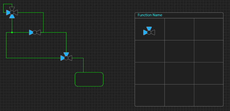
This actual screen dump from BSA illustrate both User Control and User Diagrams. The diagram to left is a process diagram very common to a lot of industrial control systems. This diagram is the actual, main user interface in this case. The User Gauge to right is just an illustration made by 3 polygons and a circle on how to create a 3-Way Valve symbol. I need to work on the User gauge function, but this will privide one way to create very powerfully user gauges/interfaces.
The “Function Name” will be replaced by a unique gauge name that is listed in the left toolbar together with build-in tools. As mentioned before – BSA will contain two different tool libraries – one is build into BSA and cannot be changed, the second is user libraries. The build-in tools must be static to ensure that BSA alsways remain functional.
Since we now allow user libraries I have a second issue – what if I save a project and import it to a different computer? The obvious answer is that the saved file must be stand-alone and include either a reference or a copy of the user library. A reference should cause BSA to prompt for installing the required user library and maybe replace missing library components with a “TODO” something. BSA will compile the output checking integrity, so non-functional content should result in an error.
Keep in mind that this will give one way – not the only way – to create user symbols. The usage above have it’s limitations + you can use older user symbols to create new ones etc, but you can also create user content in old, fasion code. One obvious part here is that a user symbol also need an associated property list/tree that the user must edit.
Another challenge is mixture of automated and manually located lines – with diagrams being user interface themselves I need to care about manual control (positioning) of lines.
![]()
Also notice the small dot (above). This is a link connector and is a normal symbol that allows me to connect link lines to show what lines are connected and not. It also gives me manual control of the connect location. I can create 2-Way that rotate, 3-Way that rotate and a 4-Way version of this and I have full manual control of diagrams. I can later add auto-inserion of these to make diagrams a little easier to control – if needed. This can be used on all diagrams. As with all these ideas – I have to draft them and test them in actual usage and it is not always an idea proove to be a good one, but that is engineering for you.