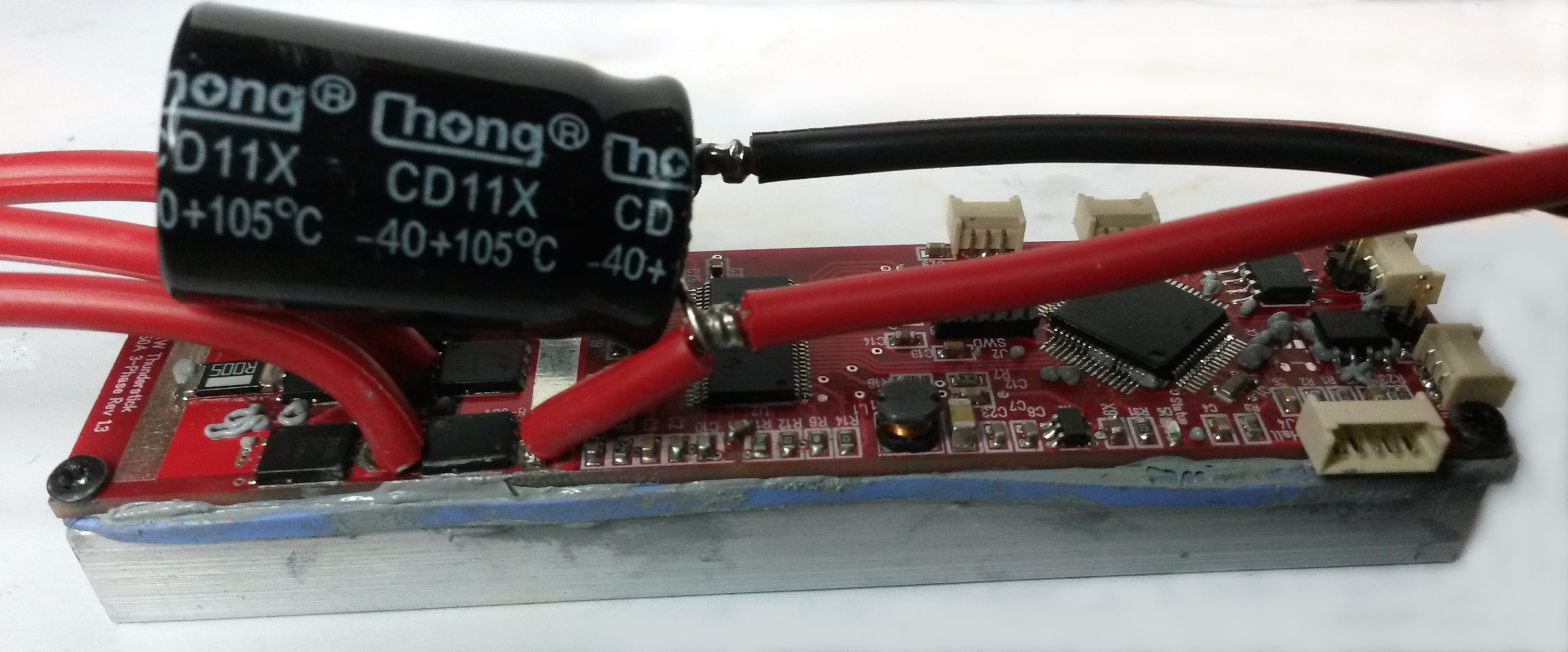
Many of you have seen this before – it’s my 60V/50A 3-Phase Motor Driver “Thunderstick”. It was a messy first assembly with greece coming through PCB holes, but I am all in all very happy with this design and will be using three of these controllers on the lawn mower. These are quite advanced drivers and similar to the Vedder (VESC) design so we can borrow that code – except that I will be using the Hall Sensors, so I need to verify if these works.
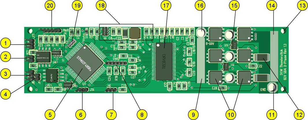
- RS485 Interface. I am seriously considering replacing that with a 2nd CAN interface.
- Terminator for RS485.
- CAN HS interface.
- Terminator jumper for CAN.
- STM32F405RG
- IO port
- IO port
- SWD. This is compatible with my other SWD ports, but it is a weird design that I will not use again.
- Power lane – designed so I can add a wire to take more current In.
- MOSFET’s.
- Ground Power In.
- Current Shunts. This only have 2 current sensors.
- Mounting holes.
- Ground power lane.
- Temperature sensors.
- +60V Power In.
- DRV8301 – 3-Phase driver.
- PSU + Buick Converter. DRV8301 contains a Buick Converter that gives 5V and we use SPX3819 to deliver 3.3V.
- Crystal.
- Hall Sensors w/5V Output.
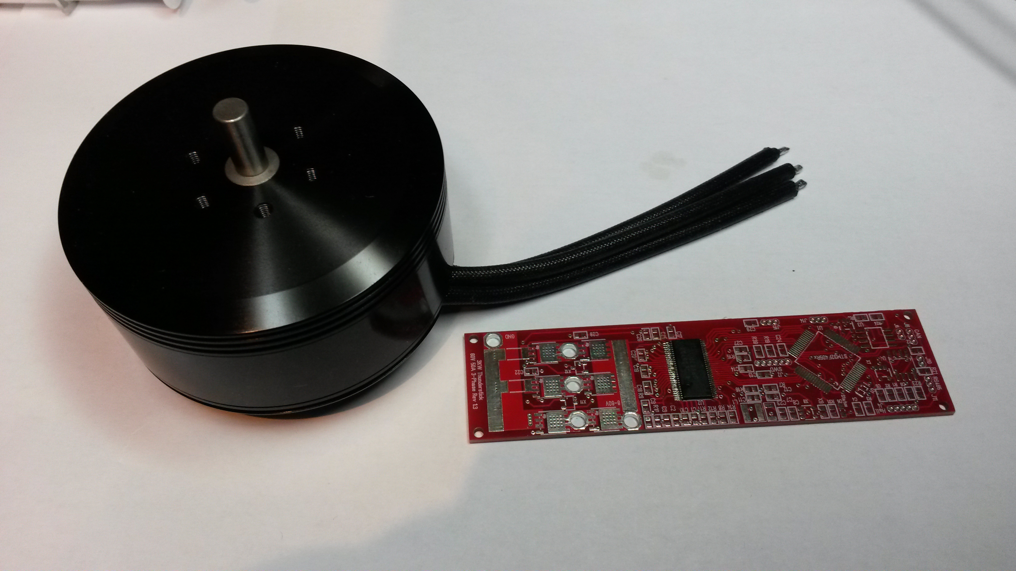
This show my drone motor that is perfect for the grass cutter.
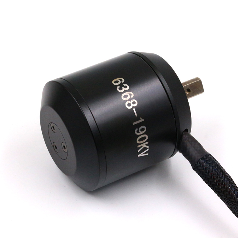 This shows the larger 3KW Scooter motor with hall sensors. The picture says 190KV, but I have 2 x 280KV. Will be running them at either 18V or 36V so I can use standard – off the shelf battery packages for DIY tools. These should fit perfectly with the wheel frames I have ordered.
I will need to make a revision of this driver and port it to KiKad in the process. At this point I also need to consider 4 or even 6 layers + I need to consider galvanic isolation as I add 3 motor controllers, several sensors and a main controller into a network.