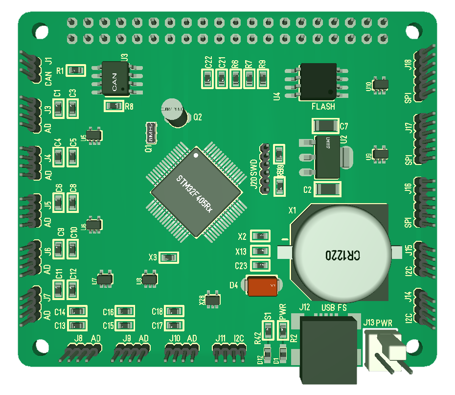
Just added the package for CR1220. The actual package look at bit different, but this has the correct footprint and size. This looks like a large component, but it is not – it is more an indication of how small and dense these Hat’s are. I will attempt to update the next revision of XPortHub with this as well.
CR1220 is a small battery that in this case support RTC VBAT. I The battery have some size on the PCB, but it is all empty space underneath so PCB routing in that area should be easy – I also added the external power connector back. What I will do a bit later is to print a PCB copy on paper and add the actual connectors as an exercise to verify that it’s not to dense. I can move those 2 led’s into the card etc. I could also move leds in between USB and Power connector to avoid that they get to close.
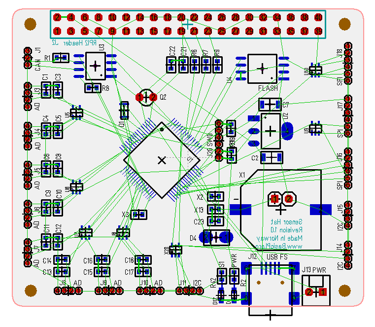
The picture above show the green lines that needs to be routed. This looks straight forward – not to many dense ratnests. I probably need to turn J16, J17 and J16 around to minimize crossed signals – but, lets see. I am still on only 2 layers so I prefer to route as much as possible on top layer and use the bottom as ground plane.
Another concern is the 6 pin SWD connector I use here. I used a 2×5 pin earlier and wanted to simplify that since some of the pins was never used. But, a 2×5 pin is easy to get female and male headers for. The only solution I have for 6 – pin is to either use a 2×5 pin adapter or add a JST Micro connector. The intention was to use the JST Micro connector, but it was unpractical to connect/disconnect + it added 10cm wiring on SWD that made it challenging getting the SWD signals working. I have to think about this, but I am considering moving back to the 2×5 pin header and specialized adapters similar to the one below.
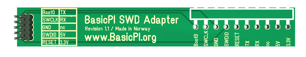
This is an SWD adapter I drafted a long time ago and never ordered. The adapter Connect between the 1.27 Pitch on the PCB and a 2.54 Pitch header that makes it easy to connect ST-Link. It show the male header, but I could modify this to connect directly to the small ST-Link SWD adapter and it should be straight forward to connect this even if a Hat is in the middle of a stack. The original design added 5V and a RX/TX, but I want to simplify this for GND, 2 SWD signals + Boot + Reset + 3.3V. I actually only need 3 pins for a SWD alone, but I need 3 extra pins to support Boot and Reset through the adapter. I have never needed Reset, but I have used Boot a few times.