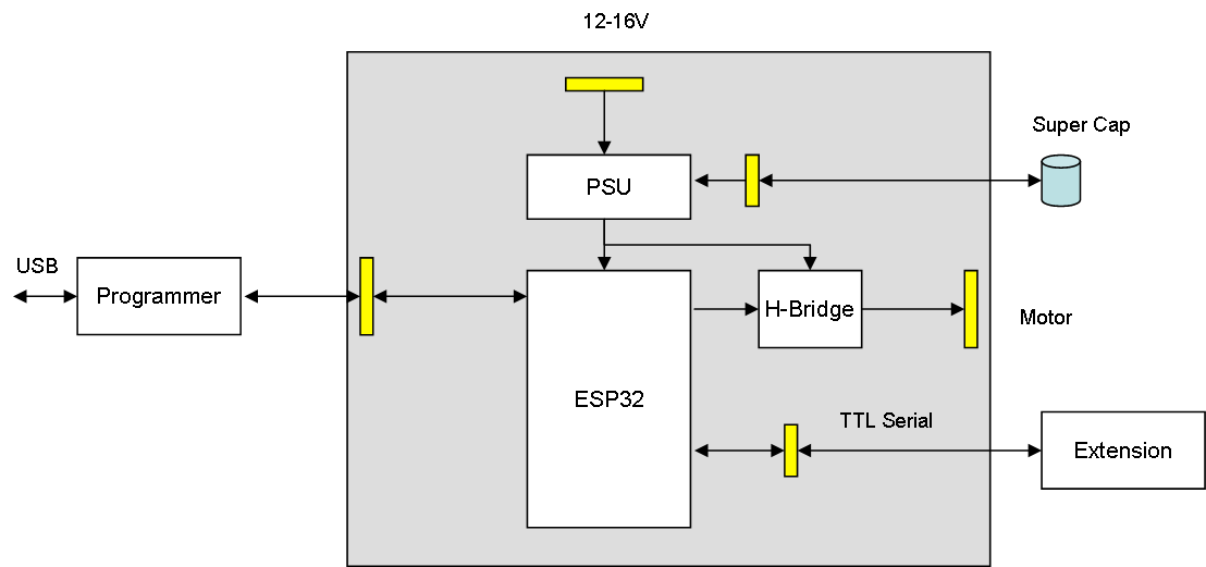
The illustration above show the number of connectors we could need on the Train Control System. I intend to use 1.25mm JST Micro connectors, but space is very limited so this will be a challenge.
- #1 is the 6 pin programmer port. It is no way to get the programmer with USB connection on the controller so I create a 6 pin program port and a separate programmer board. The intention is to wire this up so we have access to the port below the train. Once this is coded we can also use the Wifi for updates.
- #2 is the 2 pin power port
- #3 is the 2 pin Motor port.
- #4 is the 2 pin Super-Cap port. Super cap is like a small battery that will keep the system alive as we move over track gaps.
- #5 is the extension port to a 2nd controller board.
To optimize this I plan to reduce this to two connectors. One for Motor, Power and Super-Cap and a 2nd for Programming/Extension. I believe 2 connectors are doable, but I need to draw the packages and make a PCB layout before I actually know.