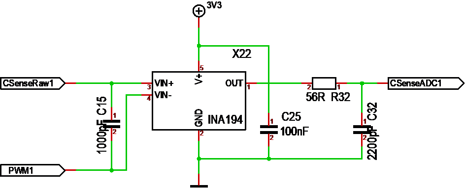
This show the new current sensor with INA194. The main reasons for changing to INA194 is that this supports -16 to +80V sensor range on high side + the chip is SO23-5 package that is a bit easier to mount than INA210 was.
C15 is a filter capacitor mounted as close to the shunt as possible. C25 is another filter mounted as close to V+ as possible and R32/C32 is a classic low pass filter. C25 is absolutely needed attempting to reduce noise on 3.3V as much as possible. The two other filters can be discussed. They can actually be done in SW as well.
I use a 0.001R shunt and INA194 do 50X gain. It is pin compatible with INA193 and INA195 that does 20x and 100X gain. With 1mOhm shunt we will get 15mV at 15A which amplified with 50X will be 0.75V. Also 15A over 0.001 is 0.225W. For a 15A design we can benefit from increasing the shunt to 4mOhm as this will be 0,9W and full 3V at 15A. Using a 0.001Ohm is actually a 50A design. The concern is currents below 1A. 1A is 50mV and max sensitivity for a 12 digit ADC is 0,007mV. In theory we should be fine, but I am worried about the signal/noise at these low currents. I will however need experience on this, so it’s nice to have gain and shunt options to play with. For a low current we should increase Shunt, but I will not worry too much about low currents on this design. I am not going to use a 3KW design to run a small, fiddly motor as I have other controllers for that.
With regards to 15A versus 50A design. The PSU lane is currently 4mm and limiting the total current usage to ca 15A. After this the PCB itself will start to heat up. I can easily fix that by using the trick of extra solder tin on the path. The 2nd limit is the lane from the Half-H-Bridge to the Shunt that will sustain 15A, but need to be a wire for 50A. If I replace this with a wire top-side I can also support heat-dissipation on the MOSFET through the PCB and a heat-sink directly on bottom side with a thermal layer will cool down both PCB and MOSFET’s to assist. I am more and more considering to just do this change, but let us see as I am also running tight on space here.
Comparing this with the MC3P design I am using 15mm wider for 1 extra channel, main capacitors on the board and temperature sensors on PCB. I would actually struggle to get main capacitors on the MC3P design at all. I want to test DRV8301 anyway for fun, but the only functionality I actually lack is the is the over-current trip in DRV8301. We can do the same in SW, but an analogue trip is faster. Assuming I upgrade this design to 50A it would not make sense to use the more limited MC3P design at all – that said – I actually want to test DRV8301 so don’t worry – I will complete this as well in time.