Current sensors are a challenge due to noise as you need to grab PWM signals. I am doing 2 things here:
- I am grabbing both current sensing and ground from the same place. directly on each side of the shunt. The EDA I use will try to include this in a ground plane, so I have to make sure it stay as a separate signals to avoid all kind of funny ground signal noise.
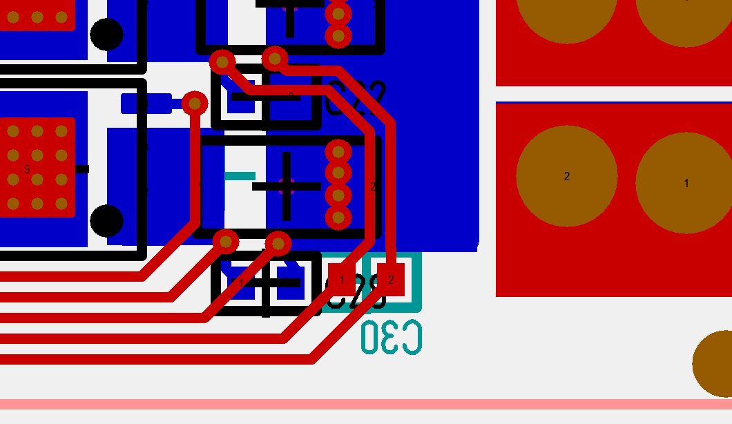
- I am adding a spare – not stuffed – capacitor on the back side for the signal that need to pass the lower PWM. I am not sure I need this, but I had the space and it gives me an option to move the filter cap to after the PWM passing to see if it makes a difference.
Current sensors are very exposed for noise and this is one place where I seriously could have needed 6 layers to shield these signals better. As this signals arrive on DRV8301 they will be amplified and used for trip alarms. On the output to the MCU we add a 2nd filter to work on noise.
If we short-cut a phase I also need to cut the motor fast – very fast. I can’t stop the first PWM as we need that to detect that a phase is shorted, so how many PWM output’s can we survive with Rt and Rs being our only resistance (2.9mOhm all together)?
Answer : I don’t know! If you do that math with 60V you will realize that a shorted pulse is an insane 20.690 Ampere. Assuming you have 10% PWM duty that is still some 2000Ampere that instantly will fry a MOSFET and Shunt, so to have any chance we will need to react on the 1st PWM and have cut the MOSFET’s on the 2nd. What will help us here is that the PSU that feed us have a limitation and analogue trip. The worst scenario is actually if we are connected to a battery because some batteries will actually support these insane pulses.
Back to the filter – this is why you might not want a hardware filter at all because it delays this signal. If you filter in SW you can still respond to a single, insane pulse, but that short-cut is also almost 21V over the shunt so I am happy DRV8301 is in the front-line here.
DRV8301 do actually have an analogue/logic trip, meaning that if we short-cut we also cut PWM signals based on a different response speed than we can achieve in SW. But, what about the 3rd phase?
This is one of many reasons I would like a current sensor on the 3rd phase. The other reason is that it gives me a capability to measure signal error on current sensing. I also have ca 15 x 5mm space between 60V and GND so I could add sensor logic here and if I move the PCB 1mm up I should also have extra space to route that sensor pass the 60V connector – some of the reference diagrams for DRV8301 show a discrete 3rd current sensor, so will look into that. I will add the 3rd if I can, but focus on this experiment is size and components on top layers only.