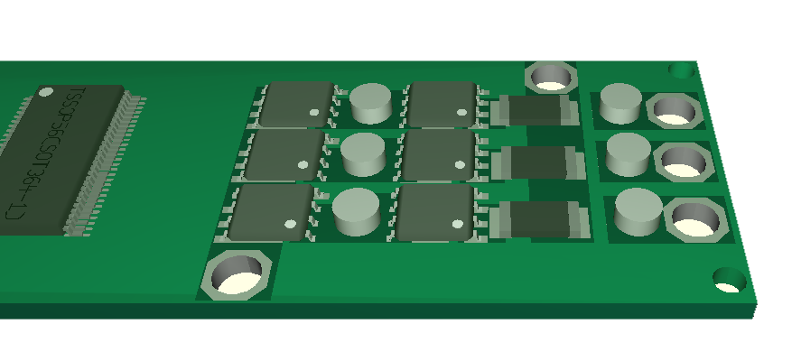
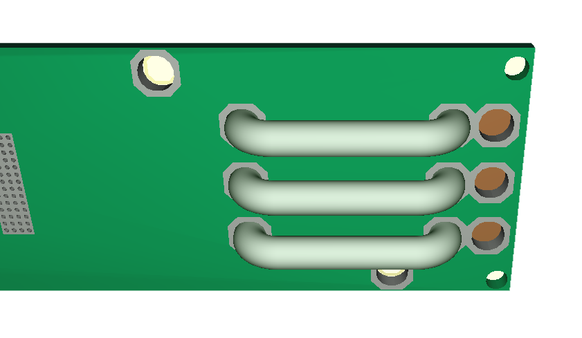
This is a mock up of routing 50A out from a small PCB with 2 layers. I use 3mm wire as “high side” shunt on bottom to get to the right where I can connect 3-Phase. This leaves MOSFET’s and current shunt’s on top. I also get heat-sink if needed on top covering both MOSFET and Shunt’s. I should not need heat-sink up to 25A, but I will need a small heat sink to get rid of ca 8W in total over MOSFET’s and Shunt’s at 50A. I might very well have to limit this to 40A.
I will need between 90-20mm to 100 to 25mm to route this BLDC controller, but this is a 60V 50A design delivering up to 3000W.
MOSFET’s are 1.9mOhm so 50 will dissipate 4.75W in total in DC mode, but since this is a 3-phase we will in average have 16.7A per MOSFET which is 0,5W. This should actually be within what we can dissipate without heat-sink and these MOSFET’s have 400A pulse drain and 160A limit, so I could be getting anything between 30A to 100A++ out of this design. 100A/3 over 1.9mOhm is in theory 2W – which is doable – not sure. At this point I just need to test and see where the weakest link is. 3mm wire is sufficient for 50A, but I will need to increase this for 100A.
How do I test a 50A to 100A controller? First challenge is actually to buy a motor that will cost me ca 200.- USD. The second is to build a PSU. My largest PSU is 50V/20A, but I can test 60V and Max A independent using a 12V LIPO for the later.
I better get a fire distinguisher prepared before I test this.
Another Win on this design is that the left side with MCU, DRV8301 and Communication easily can be separated out as the controller board for even larger Motor Controllers. And no worries – I am still keen on making a sized Down Controller for 15A and 2-3A.