These small, advanced controllers are a bit more work to route than you expect, but I managed to add two extra connectors as well.
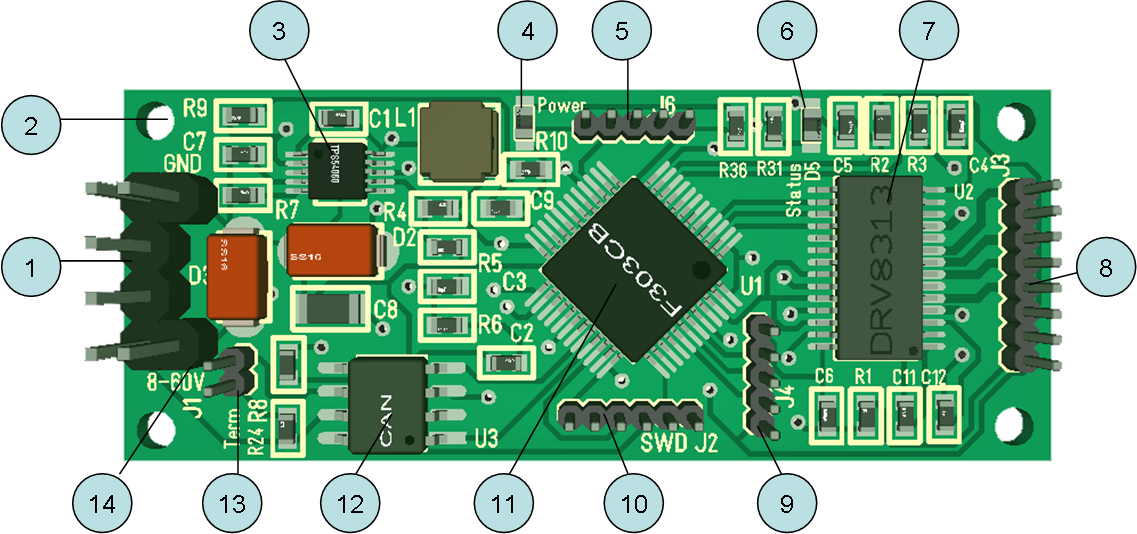
- J1 – 4 pin 2.54 pitch connector with Power and CAN.
- 4x 2mm mounting holes.
- 60V to 3.3V DC/DC regulator TMS54060.
- Power Led.
- J6-Analogue or SPI connector.
- Status Led.
- DRV8313 with build in Gate Driver and MOSFET supporting 8-60V and 2.5A.
- J3-Motor and Hall Sensor connector.
- J4-Digital IO/UART Connector.
- J2-SWD Connector.
- STM32F303CB with 128Kb Flash, 40Kb SRAM. Full 32bit M3 Arm ticking at 72Mhz.
- CAN Tranceiver supporting SN65HVD233, but can also use SN65HVD230. 1Mbps and slope control as well as 3-state and programmable loopback (HVD233 only).
- J5 – optional 120 Ohm terminal resistor for CAN Network.
- Extra holes on power to add large capacitor needed for motors.
It will be around 2 months before I can work on this, but I should get a new batch of MOSFET’s for MC4X15A arriving any day allowing me to continue on this controller while I wait for this one.