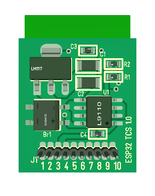
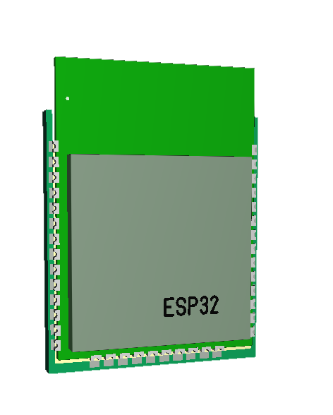
This shows the new Train Model Control System based on ESP-WROOM-32. The full size is 19.5 x 26.6 mm. The old one was 20 x 30 and I needed to cut it down from 30 to fit in my smallest cockpit.
Pin 1,2 & 9 are GPIO. Pin 7 & 8 can also be used as GPIO.
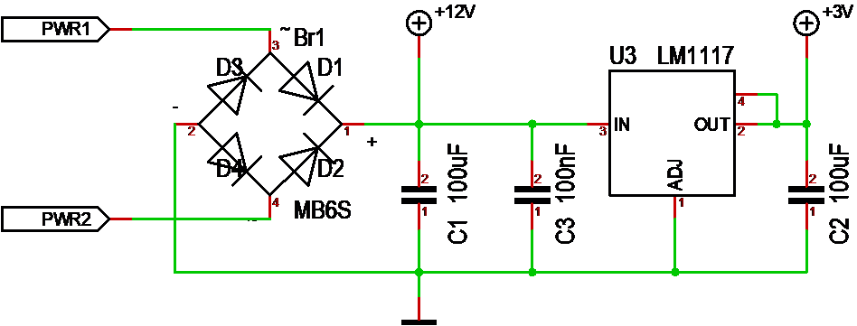
Pin 3 & 4 are 12V AC or DC Power. I am using a small rectifier bridge even if I only plan 12V DC. The 3.3V Regulator is a classic LM1117.
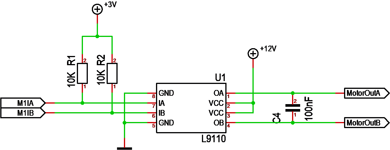
Pin 5 & 6 is the H-Bridge using a L9110.
Pin 7 & 8 is the UART for programming the ESP32. This is basically only needed for first time factory config, so 5&6 can be used as GPIO pins.
Pin 10 is Ground.
Notice that it is 3mm pads on the connector so wires can be connected on the surface, but it is also possible to attach a pin header with some work. It can’t go though so soldering the pins will require some care.
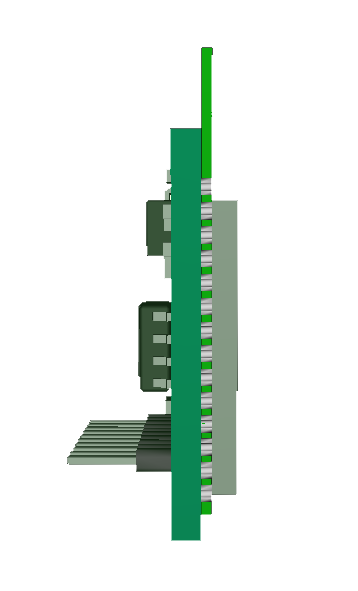
The design require an isolater tape between ESP32 and the PCB.
I have never programmed one of these, but I believe we just set the Wifi correct and work through this. The UART ahould only be needed as backup – but, we will learn as we go.
I will wrap up full schematics and gerbers later, but I prefer to do that after initial testing.