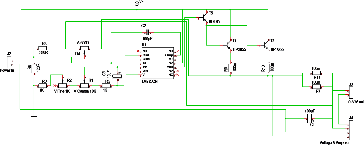
This is the schematics for the regulator side of the Lab PSU. I am using the classic LM723 in this design which allow for current and voltage adjustments through potentiometers. T1 & T2 deliver a max of 15A each, but current will be limited by the shunt resistors R14 & R7 as well as R9 & R10.
I have kept this circuit as simple as possible to give a modular, small analogue regulator. It exist plenty of doc on LM723 and example schematics on the net. I actually need to assemble this on a vero-board to verify the values I use on resistors.
What is not shown here is the capacitor board. I am recommended ca 1000uF/1A out, so I designed the cap board for 20,000uF + TVS diode. The issue with a separate capacitor board is that everyone can adapt to their own. I also realize that I might need a capacitor board between the regulator and relay board to smooth out spikes as the relays connect/disconnect. capacitors on the out path also have a second objective to protect the test equipment from it’s own nasty spikes (if it has some).
The reason for using hole through technology on this project is because it enables more hobbyists to build these themselves. I will provide access to PCB and detailed BOM lists as soon as the design is verified.
Looking forward the next step is to build one of these for verification. Part of that will be load testing and looking at ripple & noise on the output. With the regulator being a module I also have the option to use a ring trafo for a full analogue design to reduce noise if this still is an issue. The noise we talk about is PWM from the switched regulators in front. Some test equipment might be sensitive to this. I am very curious to test how good this old analogue regulator is as a end step. The classic PSU will need two of this so you can create -30V to +30V.