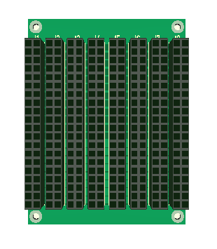
This is just an early 3D model of the minimum backbone bus just to illustrate and work on practical issues. I am going for the more minimal bus for now. The size of the bus do not decide the size of the boards, but I do like this small size. I will however adjust the actual size to practical applications.
What is missing here is a better way of interconnecting several boards and connecting to the PSU. But, I am happy with the PSU lanes – I had no problem using 2mm wide lanes on each side for GND,12V,24V,48V on both A and B. Simply said we can handle some currents in the backbone.
I added 8 slots expecting that we will use 4, but I also miss mechanical fittings of the IO boards here – as I plug IO boards in I need a mechanism to hold them in place.
It is several design considerations that is not solved yet – vibration, interconnection between boards, fixing of sub-boards, connection to RS-X networks etc. But, we need to start somewhere.