I really like routing electronics. It is something relaxing about this task that I find very enjoyable. I started routing on pen & paper single layer some 30+ years ago, so having access to a professional EDA and 2 layers are a dream. I would like to upgrade to 4 layers to get two layers assigned to ground and power to increase signal qualities, but I am amazed with what I get away with on 2 layers.
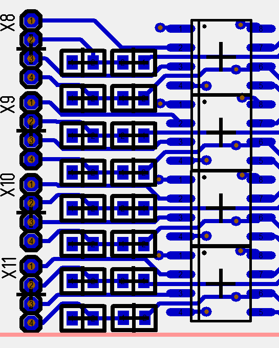
This is the filters, TVS and protections circuitry on the 4 x Half Bridge driver connecting up to the terminal connectors. I decided to make a combined board with MCU and jumper to take out all signals for now. I will simply avoid mounting everything for some of the tests.
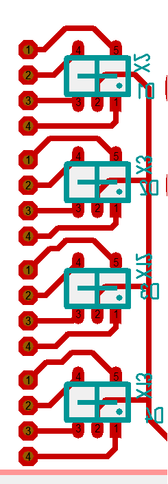
This is the backside of the same Connectors. One of my challenges was space as wanted to add a 6,1V TVS diode on every signal Connected between the driver and the MCU due to the effects involved. I did not thing I would make it, but as I looked at the terminal jumpers that are hole through I realized that I could just attach a 4 x TVS array on the “other layer”.
It don’t look much as it is done, but it actually is quite a bit of work before the rat-nest of wires come nicely together. In this case I changed schematics to adapt it to the PCB. Having terminal Connectors like this between driver and MCU also makes it easy to use these as tes poits connecting a Logic Analyzer/Oscilloscope. I will need an adapter board due to the tight 1.27 Pitch thought – I will be back with a complete board a bit later.