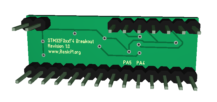
I actually bought a breakout board for STM32F030F4 and discovered that it could not be mounted on a bread-/vero-board. I prefer making proper PCB’s, but I use breakout boards a lot during concept testing. This one is breadboard friendly and can either be mounted standing up or with both sides down. The connector on top contains SWD using 2.54 pitch this time, but the same pin layout as the separate SWD.
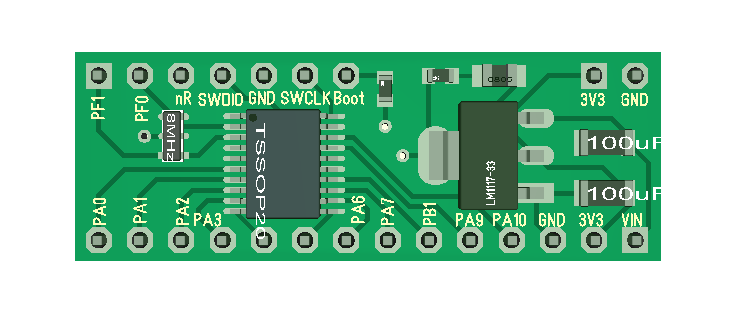
The content on the board is a bare minimum consisting of MCU with x-tal, SWD (top) and a 3.3V PSU (AMS1117). All Connectors on the STM32F030F4are available.
PIN Layout is as follows:
| PA0 | PF1 |
| PA1 | PF0 |
| PA2 | nRESET |
| PA3 | SWDIO |
| PA4 | GND |
| PA5 | SWCLK |
| PA6 | BOOT0 |
| PA7 | – |
| PB1 | – |
| PA9 | – |
| PA10 | – |
| GND | – |
| 3,3V | 3,3V |
| VIN (5-16V) | GND |
The benefit of a 2.54 pitch SWD connector is that I avoid the extra breakout board and having the pins to mount thos board flat down if required. The drawback is size and that I loose out on just connecting without to just program the chip. I usually prefer the smaller SWD connector, but this is a special case.