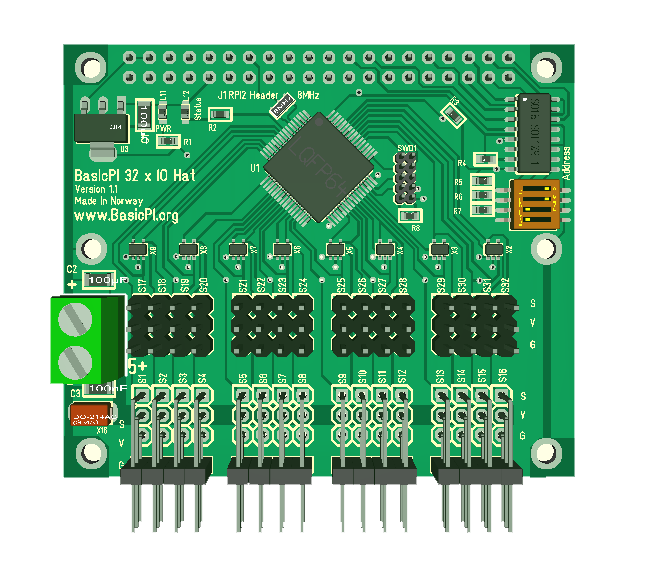
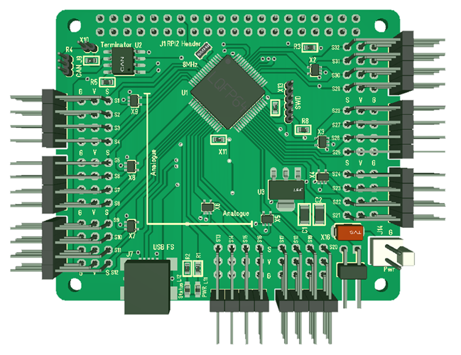
These two 3D models show my old and new 32xIO. It’s a layout difference, but except for that they are mostly identical. The old board have the DIP selecting CS Pin for SPI, while the new dropped that.
 |
 |
|
Revison 1.1 |
Revision 1.3 |
The challenge with these 32xServo ports are that I do not have 32 PWM signals in HW. In theory STM32F405 do have 32 x PWM signals, but you can’t route them all at the same time. At most I get 28 signals if I switch everything else off – which I can’t.
The idea was to use a timer interrupt to bit-bang some of the pins to compensate, but to do that we need to actually use the MCU a bit. The classic RF pulse is 500uS to 1500 uS, so we need something like 50Khz interrupt or preferable 100Khz interrupt to process with some accuracy. I would have preferred using PWM signals only, but that is not possible. Also, we do actually have a powerfully M4 ticking at 168Mhz to support this, so we have plenty of juice – we can do this. The test is to put signals on a Servo and watch their behavior as they hold selected positions. I tried that with SW on a ESP32 and noticed “twitching” – small movements before I switched to HW PWM channels.
The way it is routed on 2.3 means I have:
- 32 x GPIO channels since all are GPIO.
- 17 x 5V compatible GPIO channels
- 15 x ADC channels
- 22 x Hardware PWM Channels.
- 1 x SPI port for backbone bus
- 1 x CAN port
- 1 x USB port
- 1 x User Led
I do however notice that I can optimize this a bit:
- I have used PC1 which is ADC capable for Status Led, while I have PC13,14 and 15 that are GPIO only available. This gives me one extra ADC channel, meaning I get all 16 ADC channels on IO.
- PC13, PC14 and PC15 can be used for Led’s giving me 3 user leds.
- PB12 and PB13 can be used on CAN2 releasing PB9 and PB8 from CAN1. That gives me 2 extra PWM/GPIO channels replacing 2 x GPIO only channels. CAN2 is Slave only thought, but I think I can accept that.
- If I ditch SPI1_MOSI and accept that this board only can be used as Half-Duplex Slave will free a PWM capable pin. I have to think about this one.
- In addition I need to add resistor options on SPI as well as the new SWD connector.
- Replace 2.54 pitch jumper with a 1.27 pitch.
- Move + Power lane away from ground plane looks doable to get a better ground plane.
- Move USB connector to right side closer to PSU.
- I also need to evaluate capacitance on the power connector.
- That leaves one change – I need different PSU on the 16 first versus the 16 last. Or more correctly. I think the solution here is to add an option to select between 3.3V/5V or Servo PSU on the 16 ADC capable channels.
I guess I can as well just start re-wiring this PCB from scratch due to the number of pin changes. But, I think this will be worth it + it is not that much work once I set my mind to do it. It is actually far more work making SW, but again – the changes will only affect the “wire” function and capability list. Done right Rev 1.4 should have:
- 16 ADC/GPIO w/Mixed HW/SW PWM to left
- 16 GPIO w/ HW PWM to right