Rev 1.3 of my LoRa/GPS Hat. It will be a Rev 1.4 before I order this PCB because I want some changes. I want to remove (11) the UART port and (7) the separate Power port. The 5V power port will be removed on all Hat’s as I want to force 5V through USB or a separate PSU board. Having a separate MCU Power connector on each board is just occupying space and I need to be more consistent to separate MCU power and Motor power on those boards that need both.
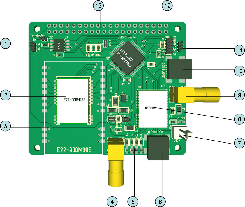
- CAN Tranceiver
- LoRa 125mW Tranceiver. Covers between 3-6km of range.
- LoRa 1W Tranceiver covers up to 12Km of range.
- LoRa Antenna port
- Leds
- Standard USB
- MCU Power
- GPS Module
- GPS Antenna port
- GPS USB Connector
- UART
- SWD
- RPI Connector
I have the modules, I also have the Rev 1.0 boards, but I did a schematic error on 1.0 and I have so much to do so I will make Rev 1.4 and order new boards before I assemble this. A last change I am considering is to remove the E22-900M30S which is the 1W version. But, I will leave it on for now since I have a few modules anyway.
This board is quite flexible as I can switch on LoRa and GPS separately. The main reason I am holding back on assembling these units is coding – it requires a bit of coding for testing and the framework is in the pipeline, but I focus on XPortHub to build basic libraries/infrastructure.