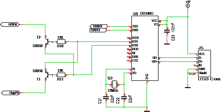
Part 3 of the Train Controller will go to a separate USB card we need to connect for initial programming of the ESP32. On this we connect GPIO0, ChipPU and the default UART. This is needed to program and develop the FW on ESP32.
The USB chip is a CH340G. Most other designs will use a FTDI chip, but you will not see a FTDI chip in any of my designs. That Scottish company bricked my 3D printer a few years back and I simply dot trust them + CH340G is low cost, well supported and always work.
This schematics is borrowed from the utility driver. I think I can use it “as is”, but I will add a separate 3.3V regulator to feed the ESP32 power from the USB while programming. This means I need a 6 pin programmer port with +3.3V, RX, TX, GPIO0,ChipPU and GND. I will make a micro JST on the board and maybe an optional connector board that can be available under the train so we can connect without direct access to the control system. This is because I need some flexibility around hiding parts of the system in small locomotimes.