I did a few prototypes to test a graphical programming language a few years back. First one in VC++/MFC and later one in C#/.NET. What I will do next is to write blog entries discussing the syntax and wrap this up as a language specification.
I called this “Plain Logic Diagram” (PLD) by accident and I will use that name for now.
We have already described Plain as an assembly language, so this is a “compiler” that generate Plain assembly. The syntax is based on a combination of classic Flowcharts, SDL (Specification and Description Language) and some new concepts to take advantage of graphic diagram qualities.
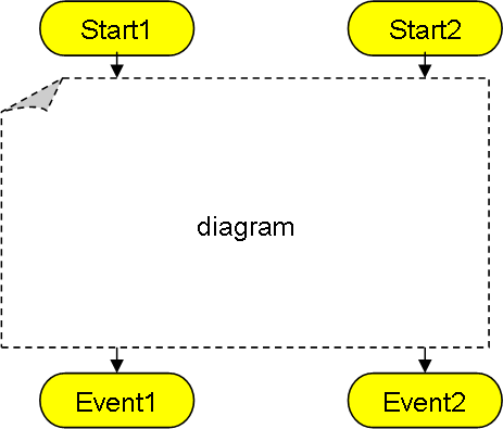
The illustrations I use will have to be created in various tools, this one show the terminators of a diagram and is drawn in PowerPoint.
A classic function have a start and an exit. We already know that Plain raise events with different output parameters. In the diagram this is shown as multiple exit terminators with associated parameters. The new part is that we also have multiple input paths with different parameters in the same diagram.
The key principle here is that one diagram is a function with multiple entry points and multiple exit points. Exit points are event’s that either are Static, Optional or Mandatory.
A Static event is a hard-coded jump to another diagram that can not be changed.
An Optional event also have a hard-coded default that the user can chose to override as he uses the function.
A Mandatory event must be present in the diagram using the function.
These are the same principles we decided on for Plain assembly events. In the real diagram we will add notifications to visualise these.
A diagram is the same as a “function”. Off-page connectors can only be through terminators, but a diagram can be as large and complex as you want. Logic is flow-chart like and will be instantly recognized by most people. This diagramming technique have been tested as executable specifications and have proven itself as a superior specification technique in front of customers. The only drawback is that you need a specialized tool to do this otherwise you just end up using far to much time creating diagrams.
So in short – the IDE and language goes hand in hand. A graphical language can only exist if we create a proper IDE/Tool for it.
The diagram example shown here do however suffer from the issue that I can’t see the parameters. I see high level logic, but I don’t see the actual executable details. Also – what about local variables etc?
to be continued…
