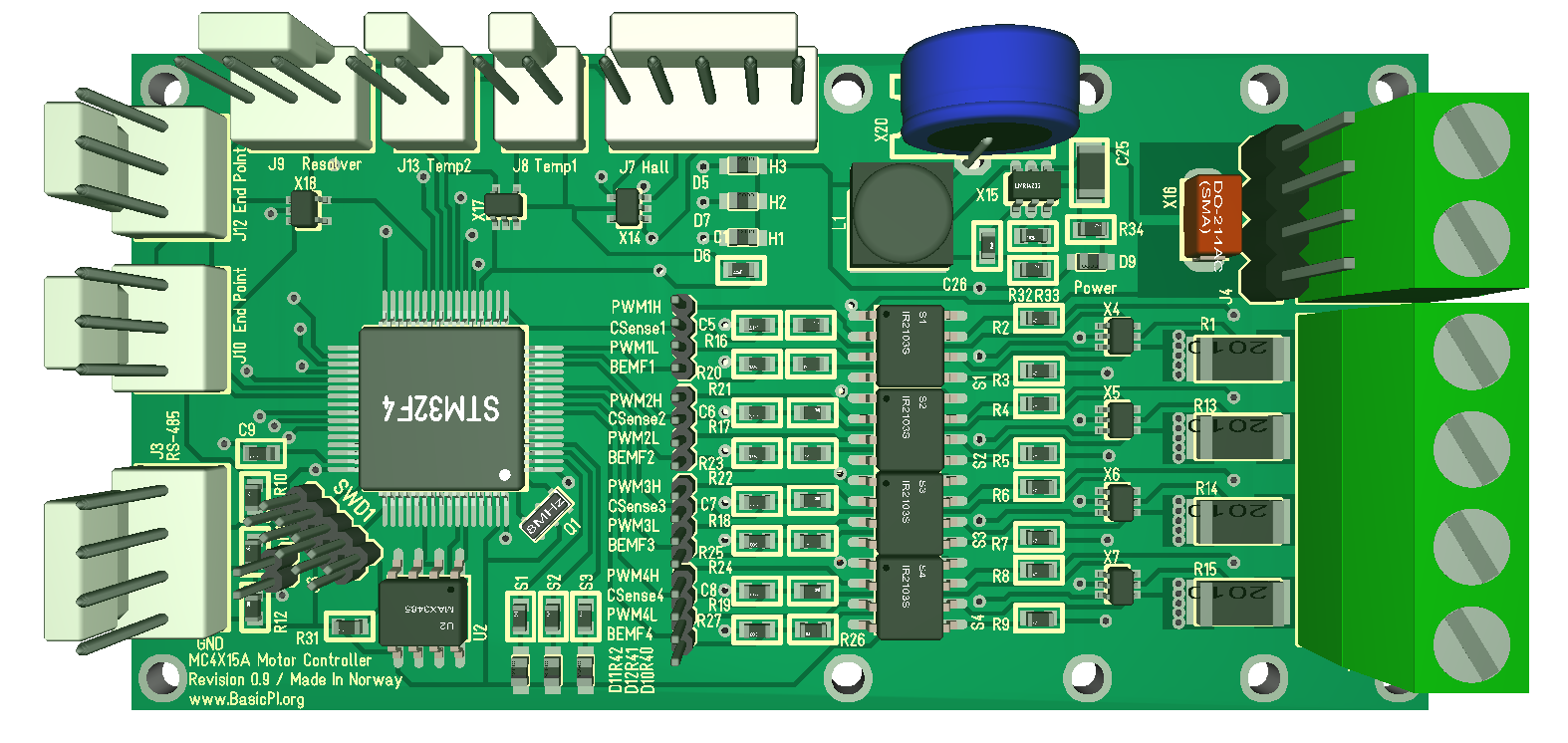
I designed this universal motor controller capable on driving DC-, Stepper-, BLDC- and even AC – motors earlier. The design parameters was 12-24V at 15A. This is quite a capable controller, but I did a mistake that limit the controller to 12-20V since I connected the Gate Drivers to the Motor PSU directly. To compensate for this I need to modify the design and implement a separate 12V PSU. As I correct this I also want to consider some additional changes.
I am considering is to replace the RS485 with an isolated RS485 due to the amount of energy involved. The 3rd change is Ethernet on a separate adapter board. Basically I want to copy the modules I use on the Universal Adapter as soon as I have tested them.
I am not sure about Ethernet. Ethernet sound nice due to the functionality, but it is a clumsy, 4-wire 1:1 solution. RS485 is slower, but it is a 2-wire network. It actually makes more sense having dual RS485 to be honest. CAN & Ethernet is easier to deal with using an adapter board- RS485 is considered a lower level of communication than CAN because CAN have protocols like CANopen, J1939 etc. The reality is that if we use RS-X that changes.
What I probably should do at some point is to create a “Ethernet” on top of RS-X by using a dual RS-X connection. But, that is fun for later…
So the modified design will be
- STM32F405RG MCU, 168Mhz, 32bit M4, 1MbFlash, 192KbSRAM
- 4 x separate half bridge drivers, 30V @15A
- Current sensors on all
- BEMF sensors
- PSU Voltage Sensor
- Separate 3.3V supercap to sustain MCU in power dips.
- 3 x hall sensors
- 2 x temperature sensors.
- 1 x resolver
- 2 x end sensors
- 1-2 x RS485
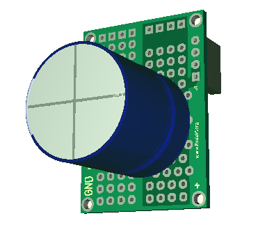
- Adapter board for battery/caps
- Adapter board for CAN/Ethernet/Wifi
Applications
- Solenoid driver
- DC Motor driver
- Stepper Motor Driver
- Brushless 3-Phase motor driver