Wow – it is actually ticking -at least blinking the leds. Been a bit forth and back – this is a STM32F105RB – I connected it using zero resistors on the VCAP as I could not get STM32F405RG to work. Turned out the problem seems to be my Mini ST-link’s. Well be back With STM32F405RG, but this was a struggle to get ticking!
Update (28.mar.2017) – F105 working well, but F405 still not ticking. According to my notes the only difference should be two capacitors from pin 31 and 47 to ground. My challenge with this board is that it is quite small, tight and contains 7 new modules that I have not coded before. This could be a test of my electronic skills.
I still suspect bad soldering that tend to be the case – this is the drawback with hand-soldered prototypes – so I will make a fresh attempt later – these MCU’s have been dead easy to get going so far – connect power and a SWD and your up. I can’t complain – I had a pretty free ride getting very over-confident so far
Update (29.Mar.2017) – It is still a mystery why the F405 will not work. I applied the 100nF capacitor on NRST, but it made no difference. I did however discover a soldering technique to minimize shortcuts on these LQFP packages. As for the board – F105 is working perfectly if I replace VCAP capacitors with zero resistors, so the board is ok – I don’t need the F405 for this board, but I wanted to test F405. I still have a few things to try. I have MCU’s from two batches, so I will start fresh on a new board with a different MCU batch later.
After that I will update my Rx breakout to have VCAP capacitors and jumpers to use both F1 and F4. It should be this simple. A breakout board is better to do this level of testing on as I need a proof of concept on a F405.
I did test my ST-Link on a F407 and it worked fine – this is more or less the same MCU. The initial error was “No Communication”, but as I removed one MCU and fixed a shortcut the error change to “Failure on Flash Erase” – I have seen this on other board that I later got working with F105 as well. This means it has some initial communication with the MCU, but the erase operation fails. If I skip Erase it fails on Program – it sounds like an incompatible protocol.
I have four suspicions: (1) Bad/Fake batch. I am buying from various sources on-line to get samples at a decent cost, but I have so far never had a problem with this. (2) SWD wiring to long for this MCU, (3) my ST-Link is incompatible with this MCU batch. I somehow don’t think so since the F407 worked with the same wiring, but you never know. (4) I will try different capacitor sizes on the VCAP.
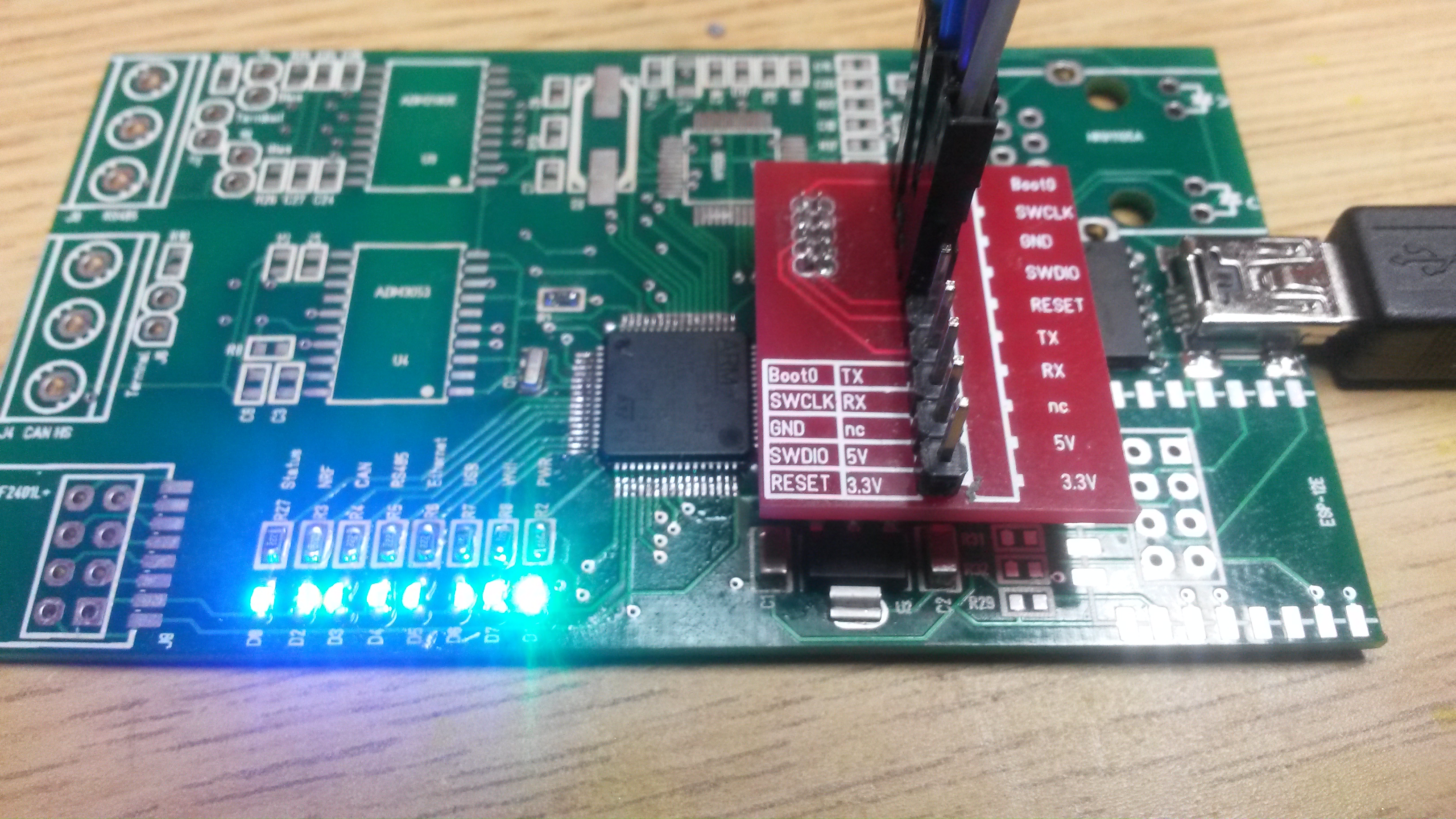
I would like to update the Rx breakout anyway, so I will order that and see how we can move on. I also realize that I need to add a few extras to make it easier to scope these boards. I am notorious for not adding test points on early proto-types and I just paid the consequence for that.
A 168Mhz design is a bit more than I want to do. But, all the high frequency stuff should be on the inside of the SoC in this case. The issue with high frequencies is that lanes start to behave more like capacitors and coils by accident, so you need a much better analogue skill-set and awareness of what you do on PCB routing. To my knowledge this should not be the problem, but at the moment I need to question everything.