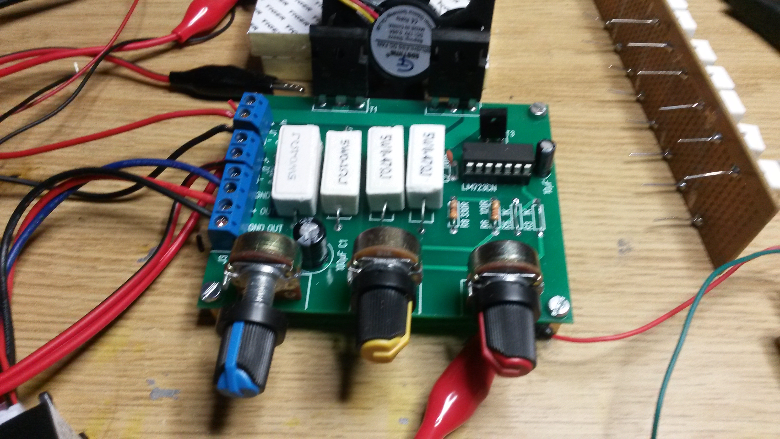
This pic shows my analogue regulator. You can see the 2 transistors and a fan in the back and my DIY load array on top left. I am actually quite happy with this after I mounted it on a proper PSU source in. The only things left is to get the current regulator working, but I am a bit handicapped in testing before I get a proper heatsink mounted. I have so far only tested 5A for a short period and had to abort as transistors started to overheat.
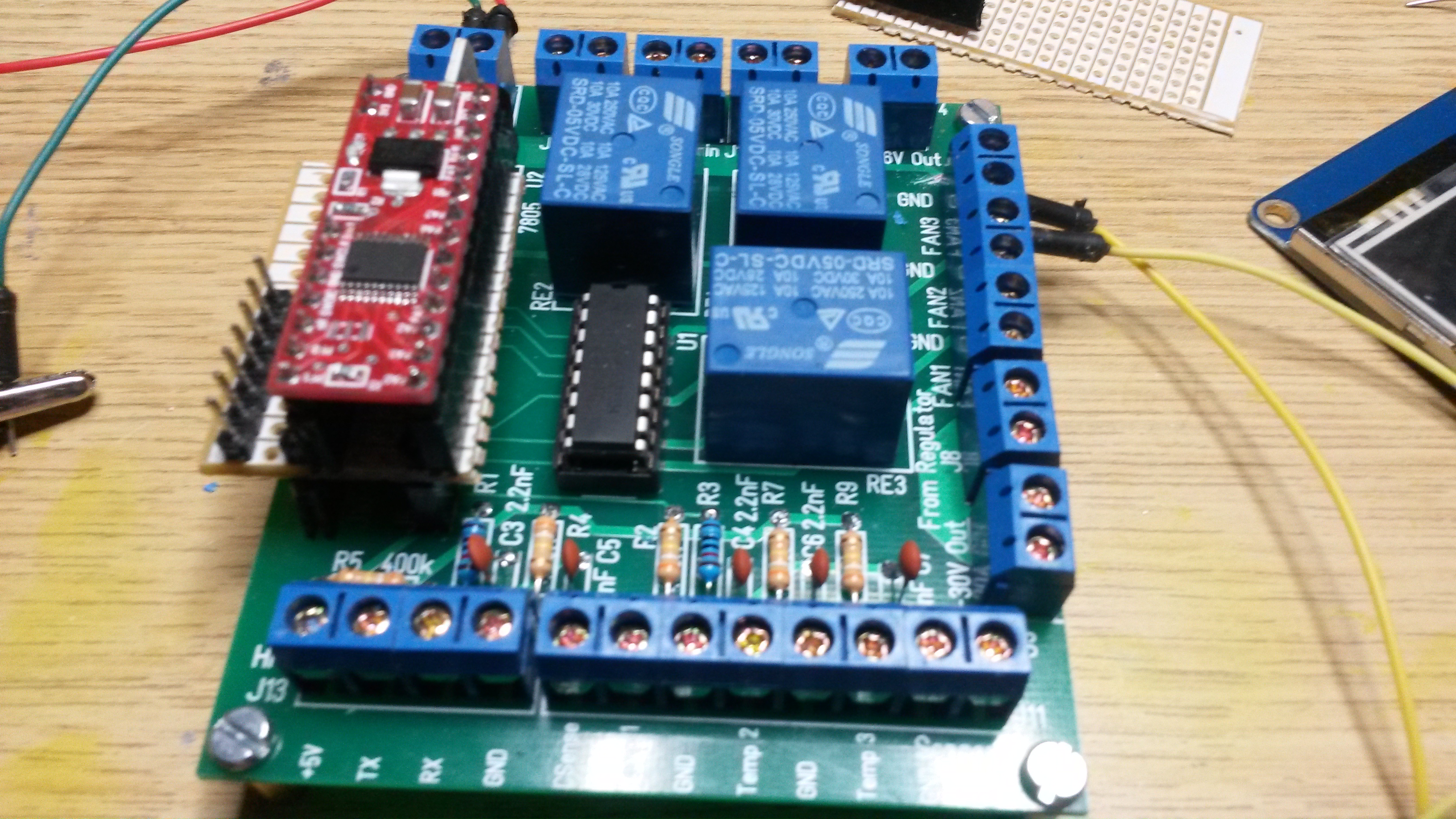
This shows my Control board. I have done more mistakes on this than I like to admit. The red PCB on left is the MCU – had to mount an adapter to allow for SWD connection so I can program it. Will start working on this a bit later. From my previous test I notice that the analogue regulator need ca 4V to work on, so I need to connect the 2nd PSU at 8V and the 3rd at ca 20V.
A few things to work on:
- Need to get current regulator working.
- Need to verify 10A continuous.
- Connected GND rather than 12V on FAN output’s.
- Forgot pull-up’s into ULN 2003 so relay’s hit in at random before MCU take control.