2P Motor with Encoder


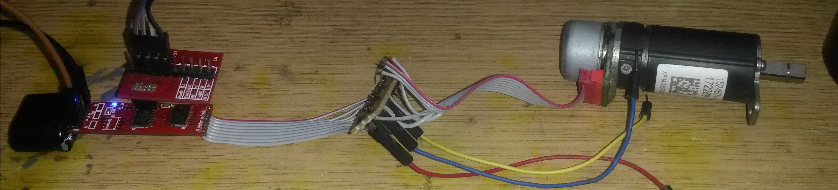
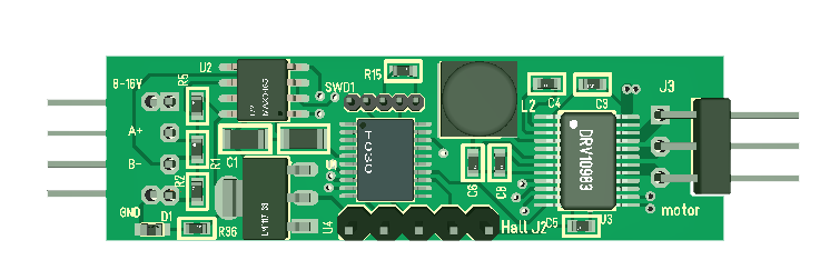
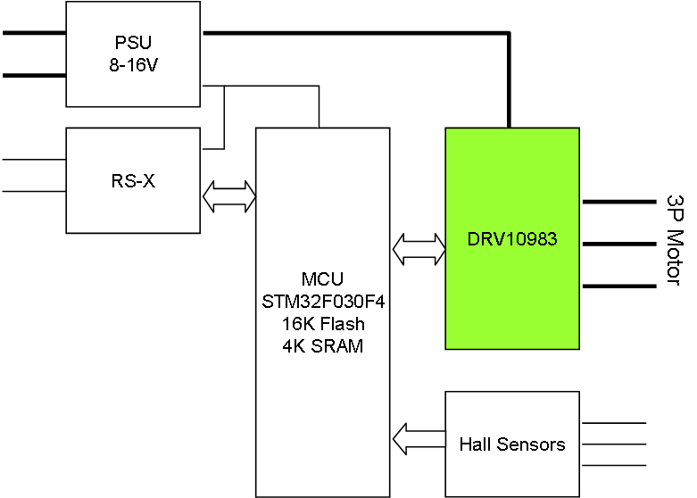
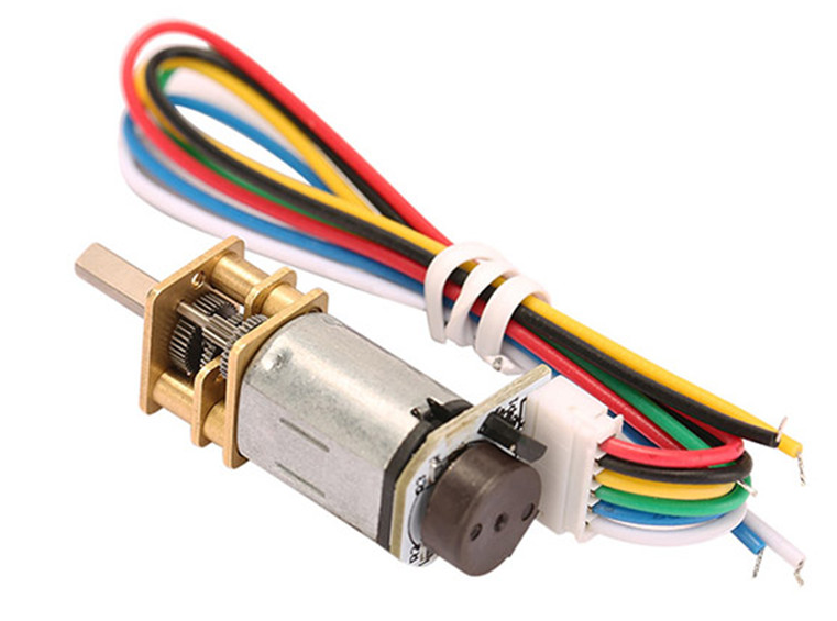
This is a classic N20 DC motor With gearbox and a Encoder. I made a micro stand-alone Control system for these, but I did not support the Encoder. The Encoder will send pulses back as the motor run indicating speed and relative position allowing us to use this as a small stepper motor.

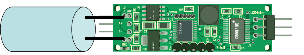
My micro DC motor Controller was a bit booring – it just worked 🙂 – in this case I want to replace the screw terminal and add support for the Encoder. I have plenty spare pins.  The only difficult issue here is the size. But, I think I will dig in on 50 x 15 millimeters With mounting holes so I get all components on one side.

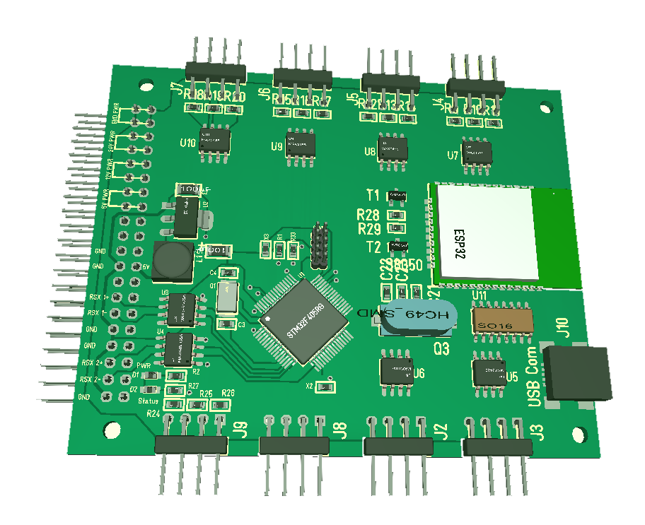
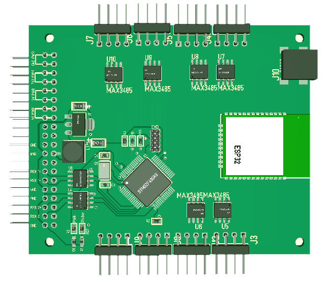
I also need to re-visit my mini PWM generator and Sensor for the same reasons – Connectors and mounting holes. I admit I focused a bit too much on size alone then I made these.

Another Component is to make a ESP32 With battery capable of switching on/off these as well as operating them – I need to think about that a bit because I could also just use the ESP32 and add the size needed replacing the STM32F030.

Mini BLDC Controller Working

Had a heck of a job getting this to working – seems like I was doomed to do all possible mistakes. First the SWD Connector on the pic is connected wrong, after that the cable was swapped around and finally I banged the wrong pins. To even make it worse I did not manage to get MCU pins working with the CubeMX, so reverted to CoIDE and old libs and voila…

At the moment I am controlling speed through PWM duty cycle and it Works “ok”. 3.3V is also working well giving me 8-28V range on the motor. The MCU is just ticking on 8Mhz using the internal clock. The next will be to control the motor through I2C, in which case I also get to optimize with motor parameters.


BLDC Mini Controller

This is rev 1.0 of the mini Controller. I patched the 3.3V on the back-side so this is feeded 3.3V from DRV10983 and Works fine between 8-28V IN. I also added 1000uF capacitors that I hope will be sufficient to absorb sparks. I have not added the MAX3485 yet, but I can test without this.

This shows the Controller + motor Connected. The vero Board in the midle is so I can measure phases on a Scope. Time to Write some test code.

Reading the datasheet I should be able to Control the DRV10983 simply by sending a pulse between 1KHz to 25KHz. The duty cycle is the speed. But, I also have I2C Connected for the more Advanced Interface.

Mini BLDC Testing

This illustration show the new PCB layout, but the old have the same capacitor options. Previously as I tested this mini driver I did not apply the capacitor and the result was 2 blown drivers. I actually believe that a large capacitor as planned is all that is needed to absorb the spikes that took out 2 boards earlier.

The 2nd part is that I want to add a 1A/47uH coil and use the 3.3V from DRV10983 rather than the added AMS1117.

The 3rd part is to program the Controller properly to see if I can Control speed. The hard reality here is that I try running a 50mA 3-phase motor and DRV10983 is scaled for 2A motors. The driver might simply be to large for the job.

Mini BLDC 8-28V Input

This design have 2 PSU’s. One is the ANS1117 that takes up to 12/16V input and 0.5A. The second is the DC/DC on DRV10983 that delivers 100mA and allow the Circuit to be used up to 28V. I have connected both for now. The datasheet for MAX3485 indicate up to 200mA, but my own measuring indicate MCU + RS485 will use < 20mA, so lets try. I will simply avoid mounting AMS1117 and remove it on the NeXT layout if it Works.

3 Phase Motor Controller w/Hall Sensors

This is an old Project some of you will remember. I use DRV10983 from TI to provide a micro 3P Motor Controller. The MCU is STM32F030F4 that also is pin compatible With STM32F042F6. The smaller F030 provide 16K Flash while F042 provide 32Kb Flash.

I added a RS-X for Connectivity and Hall Sensors. The entire PCB is 5cm x 15mm. A bit larger than rev 1.0, but I have all Components on the same side + added a 1A coil.

The only difference between this and the earlier is the PCB layout and the selection of a larger coil. The Controller “worked”, but I only tested SPEED pin with limited success. So I need to solder up a new version and make a new test before I continue with this. Notice that 1.27 pitch cable headers are all 2.54 Pitch to deal with some of the challenges I had.

I am considering to dropping the PSU which is AMS1117. The DRV10983 do have a 100mA 3.3V PSU included that might be sufficient. It will drive the MCU, but I am not sure about the RS485.


PLC – Connectivity Module

Still an early draft, but show the 8 RS-485 connectors at top/bottom. I only use right angle headers in the 3D, but they are 2.54 pich so they can be replaced with other connectors.

I still have a few loose ends. RS485 circuit can be switched off into 3-state by setting RE High and DE Low (Neither receiving or sending). I need a similar way for the ESP32 to switch off the STM32F405RG so we can go low power. I also want a 3.7V Battery connected on the back.

I should have plenty with spare pins so we can add a few more leds etc. I do however need to solder up a RS485 (or find a breakout) and test that I can get UARTS where I want on ESP32.

PLC – Connectors Top/Bottom

This new Connectivity Module have 8 x RS485 connectors. I use the front for the antenna and USB, while top/bottom for connectors that most likely will be permanently wired.

Some users would probably request both 4-wire RS422 and RS232 and I will make a board for those later. I also need a CAN board.

As for MCU power – The MCU’s above have too much/too little. For most of the things I do they are an absolute overkill. The exception is math algorithm’s where we would need the stronger Raspberry PI. The only reason I need the STM32F405 here is because of it’s 2x10Mbps UART’s used as backbone.

Just for the record – the 3D model above is just an early draft to illustrate our options. I use those right angle headers on the 3D model, but the real can be fitted with a variety of 2.54 pitch connectors.

PLC System


One of the challenges I have is the size of connectors in front of the modules. I am actually considering using Top and Bottom on the modules to increase connector space. Another issue is that the screw connectors used on the RS485 board below is not really operational from front alone. Looking at the Servo Controller I could probably add another 16 inputs of which many would be analogue.

The GSM Module above can go as is. I am however considering replacing both SIM808, W5500 and Raspberry PI. SIM808 was chosen because it has digital voice interface, but it also cost 10.- USD and occupy a lot of space. W5500 and Raspberry PI can be replaced with ESP32.


RS485 Circuits

This is a classic RS485 circuit that I realize is not that good. It works fine, but it requires that ground always is included because of the 12V diodes.

This simplified circuit is in many ways better as we actually can use a twisted pair only. This shows a none-isolated RS-X port. I also drag both RE and DE into the MCU so we can send and receive at the same time. In fact, I could save a pin by setting RE to GND and always receive. I also avoided the leds and some 47Ohm line resistors. I also change to 3.3V version.

This last circuit is a fully isolated RS485 using ADM2582E. This includes a DC/DC and is completely isolated, but it also requires more space and cost ca 5.- USD more.