MC4X3ACAN BLDC Controller – Annotated

These small, advanced controllers are a bit more work to route than you expect, but I managed to add two extra connectors as well.

  1. J1 – 4 pin 2.54 pitch connector with Power and CAN.
  2. 4x 2mm mounting holes.
  3. 60V to 3.3V DC/DC regulator TMS54060.
  4. Power Led.
  5. J6-Analogue or SPI connector.
  6. Status Led.
  7. DRV8313 with build in Gate Driver and MOSFET supporting 8-60V and 2.5A.
  8. J3-Motor and Hall Sensor connector.
  9. J4-Digital IO/UART Connector.
  10. J2-SWD Connector.
  11. STM32F303CB with 128Kb Flash, 40Kb SRAM. Full 32bit M3 Arm ticking at 72Mhz.
  12. CAN Tranceiver supporting SN65HVD233, but can also use SN65HVD230. 1Mbps and slope control as well as 3-state and programmable loopback (HVD233 only).
  13. J5 – optional 120 Ohm terminal resistor for CAN Network.
  14. Extra holes on power to add large capacitor needed for motors.

It will be around 2 months before I can work on this, but I should get a new batch of MOSFET’s for MC4X15A arriving any day allowing me to continue on this controller while I wait for this one.

MC3X3ACAN BLDC Controller

This is a 3D model of my new BLDC Controller “MC3X3ACAN”. 3X means 3 separate Half H-Bridge channels, 3A means 3 Ampere- it is actually 2.5A max with 3.5A in peaks. This design does not include current sensors, but I have Hall Sensors since this is my target and better for low speed applications. I decided to skip current sensors, supercap and serial memory to get size down. I would have needed ca 2 cm more for that. But, I am also aware that currents sensors are very difficult to use on small motors at low speed, so it’s not a big loss. The 3D model shows STM32F303CB, but I will double check that I also can use STM32F103CB/C8. I have never used F303 before as well, so this will be fun to test!

The size is 50mm x 20mm and I am happy about this knowing that this is a 60V design with hall sensors and all components on top-side. I am not fully finished as I need to squeeze in capacitor mounting holes at left + I would like a few extra IO ports on a JST Micro Connector.

I used CAN on this for a change, but the focus here is to test my DC/DC converter as well as DRV8313. The big win is that this has all components on top layer allowing me to use the bottom layer as ground plane. Yes I can do that regardless, but I try to avoid ground planes on component sides because I get short-cuts easier ase I hand-assembly these for now. Replacing CAN With RS485 will only need 2 extra resistors.

One option that will require a bit more space is to replace STM32 with ESP32 and test the Motor & Hall Interface on ESP32. That would be a cool device with full Wifi and fun to experiment with so I will find time to do it.

60V/3.3V DC/DC

This just show the routing of the TPS54060 based DC/DC. The upper picture show the actual routing, while the lower show the real PCB once I add the ground plane. I still lack a few details to connect ground to the ground-plane in cases where ground is on a blue (top) lane. In this case I actually want to order with and without ground plane to see the difference on noise. This design is for 0.5A. I would need a larger coil for 1.5A or 2.5A. The components here are 0603 mostly, so the DC/DC area is ca 15 x 15 mm only. Learning from previous mistakes I need to add a scope test point because testing the DC/DC is one of the main objectives with this design.

Two of the resistors decide what voltage I want out which can be anything from 0.8V to 57V. I used Reference values a bit adapted, but might need to experiment to find E96 values for specific voltages. I am typically interested in 3.3V, 5V and 12V designs. I will add a separate DC/DC breakout with larger coil before I order this.

60V to 3.3V DC/DC

This is my first attempt on a 60V to 3.3V DC/DC converter. I am using the reference diagram for TPS54060 with a few modifications.

Starting at left I use a SS16 Shotky diode + a 1000uF since this is for a motor driver. You can otherwise use far less capacitance on the input. I left EN and PWRGD floating – EN is used to set under voltage shut down, while PWRGD signal if there is an error. L1 and C8 is the PWM filter and at right you have a standard Led to indicate power. C7,R7,C2,R6 and C3 are just from the reference diagram. Their values impact things like switching frequency. I need to read the datasheet properly and doublecheck with what others have done, so I can’t guarantee that this will work – but, we can give it a try!

This 3D model is the first attempt of routing a simple version of a DRV8313 60V BLDC Controller. This board is 50 x 20 mm, so it is really small and you can see the DC/DC in the red circle. I drew the 1000uF on the outside because it will be mounted as an extension fo the board. I also decided to use a coil at the size of 2x 1206 package. I should mention that all components here are on top-side. I will return to the BLDC controller itself later. This is DRV8313 With hall sensors only. This is a simpler design than the one I mentioned earlier as it lack the super-cap, current sensors and Serial memory, but it still have hall sensors. Looking at the density of the Board I probably need to extend the length a few mm as I finish it – lets see. To add the missing features I probably need another 2 cm – not sure.

I was hoping for even smaller Space on the DC/DC, but the number of components and the size of those SS16 diodes drags it up a bit, but draw a square 15 x 15 mm on a paper and you realize how small this actually is – and this is a 60V to 3.3 DC/DC delivering 0.5 to 1A.  This design is 0.5A, but I can swap out with TPS54160 to get ca 1A if I need to.

New BLDC Controller

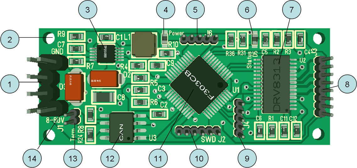
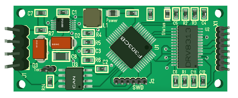
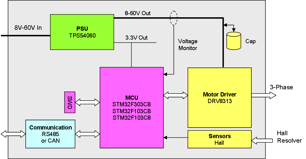
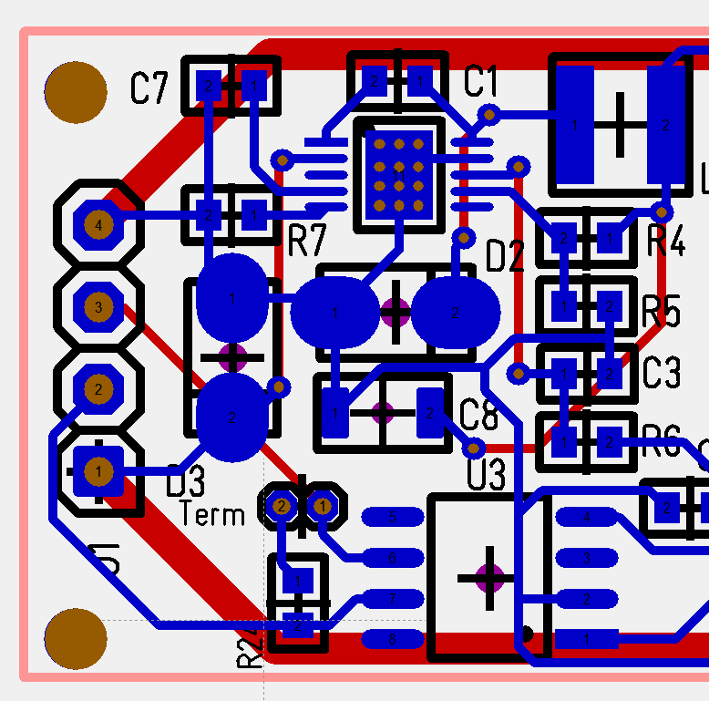
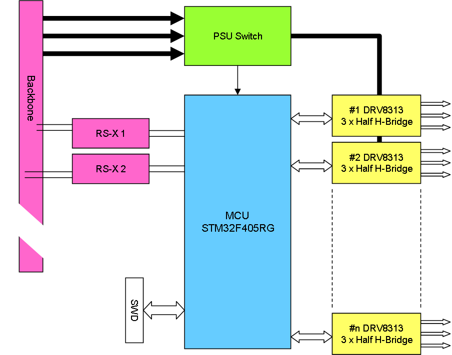
The drawing below illustrate my New, planned DRV8313 based BLDC Controller Design:

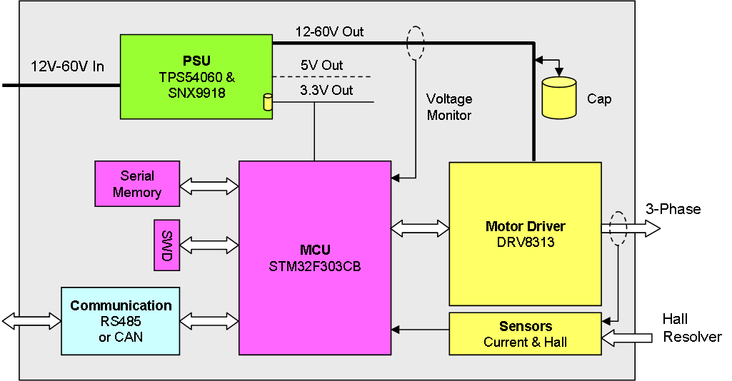
This will give a small BLDC Controller capable of 8V to 60V operation with up to 2.5A on 3-Phase motors with or without Hall sensors.

  • 8-60V operation
  • Perfect for 12V, 24V or 48V systems.
  • Up to 2.5A motors
  • Sensorless or Hall Sensor driven
  • Full FOC support.
  • Focus on speed/position control on small motors.
  • Drive 3-Phase, DC motor or solenoids.
  • RS485 or CAN
  • STM32F303 MCU

I use STM32F303CB as MCU because of their build-in programmable Op-Amps that can be connected to ADC input lines. F303 comes in LQFP48 package and is priced < 2.- USD even if it is a M4 ticking at 72Mhz. This is one of the more attractive motor controller MCU’s around. It contains 128Kb Flash and 40Kb SRAM, of which some are CCM and can be used to execute fast code.

Motor Driver will be DRV8313 that is popular on various Gimbal drivers. This allow individual Half H-Bridge driving, so it is basically just a chip with Gate Drivers, MOSFET’s and a bit of logic. It is possible to add 3 individual current sensors. Each channel can be controlled separately, meaning we can drive a 3-phase motor, DC motor or 3 x solenoid’s. But, the focus is small Brushless motors with Hall sensors that need to drive slow. 

Sensors are 1 x DC Rail sensor, 3 x current sensors, 3 x Hall sensors and temperature sensors. The idea is to have 3 separate current sensors to enable sensorless mode and individual channel usage. Current sensors on this consist of a Shunt, a low pass filter and Op-Amps on the MCU itself. Depending on available pins/space I might make available some external IO pins.

Communication is RS485 and/or CAN. I will use a new SWD connector based on 5/6-pin Micro JST.A serial Flash or EEPROM will be evaluated for storing parameters.

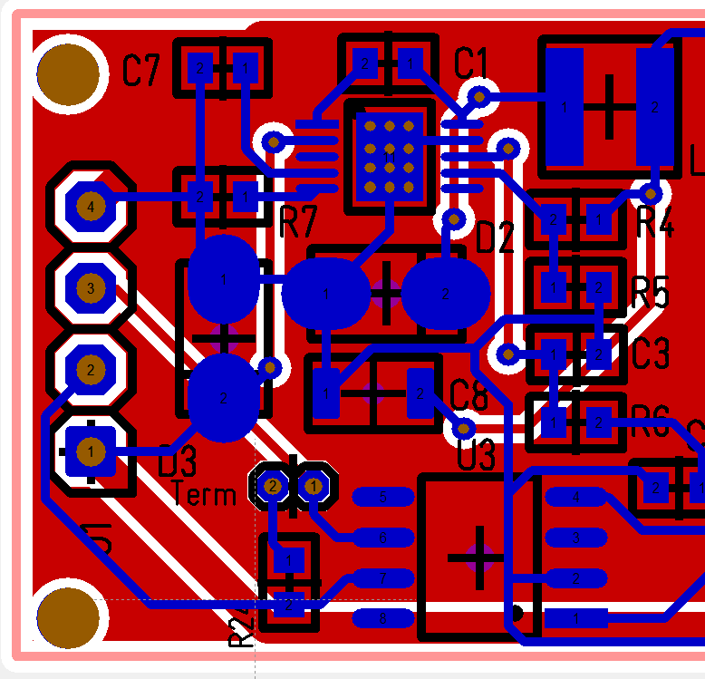
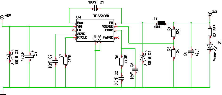
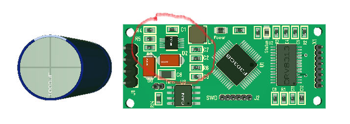
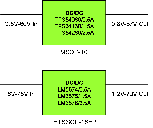
PSU will be based on TPS54060 and optionally SNX9918 if we need both 5V and 3.3V. I will try to add 1000-3300uF Caps on the 8-60V directly connected on the board and preferable between the DRV8313 and the rest of the system. I will also attempt to add the 0.33 supercap used on MC4X15A.

The name of this will be MC3X3A. The initial plan is that I will attempt a narrow controller 15mm to 20mm width and 50 to 70mm length., but actual size will be adapted as I go as usual.

As for moving on – I want to test both DRV8313 and TPS54060, so I might give this design a bit priority. I have all the components, but making this design will put my knowledge a bit. Last time I tried DRV8313 I decided to cancel the design. It was the combination of 12V limitation and size as well the plans to move on with STM32F030 and DRV10983. And I still plan to make a new, updated DRV10983 design as well. One step at the time I would also like to move on with much, larger motor controllers at some point.

Miniature 60V to 3.3V DC/DC

I found 2 series of DC/DC converters that can handle 60-75V from TI that also is available from AliExpress showing that they have some popularity. These all cost around 1.2 USD from my sources and are decently small.


These converters consist of a chip with build in MOSFET’s and PWM generator so you basically add the inductive filter and a bit of external components to adjust values. I will end up with 12+/- components on each design. Current limit range from 0.5 to 3.5A on what seems to be pin compatible devices.

Focusing on TPS54060 for now that deliver 0.5A and comes in a very small MSOP-10 package with a Pad on the bottom. I know that some of the 1206 package inductors are rated to ca 200mA and I use one of these on the DRV10983 with success. I was thinking of replacing the AMS1117 on the DRV8313 with this design and minimize size on everything. 200mA is a lot where space does matters due to total size.

60V is quite attractive for BLDC controllers as it makes it very safe to operate 48V. For an actual 60V system I would use the 75V LM5575.

Adding to this I also found a dead cheap linear SO-23 Regulator 16V to 3.3V/500mA (SPX9918). This comes in both 5V and 3.3V versions making it easy to operate with 12V, 5V and 3.3V. I will need 12V for Gate Drivers, but I might also need 5V for some chips.

What I still lack is a low cost/small space isolation DC/DC for 12,5 & 3.3V.

PLC – 24 Channel PWM Driver

This show DRV8313 used as a PWM driver on a PLC Module. This way I can get from 12 to 24 PWM channels with up to 60V @ 2A each. This gives an insane combination of 8 x BLDC Motors, 6 stepper motors, 12 DC Motors and 24 Solenoids. I need to think about this one.

In comparison with my previous module with 8 channels this will be limited to 2A, while the other can support far higher currents. But, the reality is that most stuff is below 2A and this is far more usable (assuming we can put on 6-8 x DRV8313). I do however have a problem with 24 current sensors, so I probably need to install a current sensor on the board or one per DRV8313 – lets see. I am not sure I want to make this module, but I admit that it is very tempting.

Just a quick mockup of a PCB with main components and possible connectors just to illustrate that this is very possible. Another option is that I add 12 PWM channels at top and 16 or so Analogue channels at bottom on a combined card.

Upgraded Micro BLDC Controllers

If you search for schematics you will notice that DRV8313 is far more popular than DRV10983. DRV10983 only support 28V, while DRV8313 support 60V, but the most important difference is that DRV10983 needs to be programmed through I2C while DRV8313 have direct PWM per half H-Bridge.

The 3D model above show the DRV8301 based design using a STF32F105RB, while the DRV10983 using STM32F030F4 is shown below. The size of the the driver above is 50 x 20 mm, while the one below is 40 x 11 mm.

I initially started with DRV8313, but switched to the simpler DRV10983 which is working “ok” and support a very small size. I needed 9mm more to route DRV8313, but I also supported far more on the DRV8313 design and used a LQFP64 MCU package.

I never put the DRV8313 design into test, but I actually have a load of chips and want to make a new design based on this. I like the 60V capability and the capability to use the MCU to drive the motor, I also have loads of STM32F303CB MCU’s that cost < 2.- USD and is very optional as a Motor Controller.

Both these designs have a 2.5A limitation, but the cost of DRV8313 is ca 50% of DRV10983. I will continue both designs as I also plan an upgrade of the DRV10983. I do however need to get going on coding the I2C on this and convince myself that I can control the motor speed a bit better. Next PCB will also be simpler as I am replacing connectors and removing the separate PSU.

One huge advantage on DRV10983 is the 100mA 3.3V DC/DC converter. DRV8313 only support 10mA and that is to low for a MCU + Tranceiver, meaning that I will need to find a different PSU solution. I need a 60/3.3V DC/DC supporting 100mA. I can easily use LM2596HV that do this at 3A, but that alone will be larger than the controller.

Next focus will be to establish a DRV8313 on a smaller, but decent size, while I try to minimize DRV10983 even further. And believe me, these are small as they are now! The actual target is mA Level motors, so the 2.5A range is very cool.

PLC-PWM Module

This is an old PWM Module drawing. The idea is to create a PLC module that can handle 4,6 or 8 PWM channels with 12/24V and up to 3A. I know from testing of MC4X15A that this is very doable as soon as I solve the current sensor on the channels.

The usage here is to drive solenoids, dc-motors, even stepper motors. An old hydraulic actuator will typically be driven by 2 x 24V PWM signals pulsing at very slow rates using ca 1A per channel. And yes, I can drive 2 x 3 phase motors as well since I will be using the 2 Advanced timers With 4 PWM channels each. Using the same design as on MC4X15A I actually have an option for higher currents, but this needs to come from a singlle PSU Source and I believe a max rating of 10A in total is reasonable and doable. For higher currents we need to consider specialized designs. 

I have a few advantages compared to the motor controller as I have no usage of the BEMF signal and “only” need 8 PWM signals and 8 ADC signals as interface. IR2103 can combine H&L since L input is inverted and as such be driven by a single PWM pulse. I am, not able to offer 5V PWM since the gate drivers and MOSFET design requires a minimum of 10-12V to work.  

Another advantage is that 12 & 24V is provided directly on the backbone, so I don’t need any PSU logic on the Board (except a bit of protection logic). I need to look into routing Power from the backbone to the MOSFET’s and I need to squeeze each channel into 40mm x 6mm to achieve 8. But, it’s no disaster if I reduce to 4 channels. In fact I actually consider making the PWM channel an click-on sub-board – not sure.

I will start on this as soon as I have a solution to current sensing that I like. The advantage with the PLC is that we also have 5V available and loads of the attractive sensor chips need 5V. One I would like to test is MAX9918 because it can handle -20 – +75 Voltage making it attractive for a 60V BLDC Controller later. But, I have not given up on the INA210, INA213, INA214 family yet. The INA family is ranged 26V so they are attractive for a 24V design. Their size is a pain in manual assembling, but it is a blessing in design – if I can get them to work.

The interesting part here is that we take the driver from a BLDC motor, simplify it and re-use it. The result is a very advanced and capable PWM channel.