AliExpress

I have always liked shopping at AliExpress because I get samples at 1x cost. If I buy from a distributor I end up paying 2-3x. The exception was IRF7862 that cost more for fakes than originals from Arrow for some reason. I actually realized that Arrow have very decent pricing on MOSFET’s, so might have gone a bit mad yesterday.

AliExpress did not like my chips and the pictures I sent them either. Sadly I waited to long after the first batch, but well – you win 50, loose 1 – A waste majority of sellers on AliExpress are honest and without their help to keep my cost down this blog would not have existed!

BLDC Stick 60V/50-160A

Looking for Power MOSFET’s I found (and bought) some Toshiba ones in SOP-8 format supporting 60V and 160A with 1.9mOhm RDS. This makes me believe I can make a very, small motor stick that can support 50A or higher with a little heat-sink and 30A without a heat-sink. Power dissipation is 4.75W at 50A, and this will be split over 3 sets of MOSFET’s on a 3-Phase.

This mock-up illustrates what I am thinking. A narrow stick < 10cm long and < 30mm wide supporting a 3KW BLDC motor. With Power MOSFET’s that actually are rated much higher and peaks up in 400A it comes down to 2 questions (1) can I get that currents off and (2) can I get rid of the heat?

  1. Communication Connector for CAN and RS485.
  2. Tranceivers.
  3. MCU
  4. Gate Driver DRV8301
  5. MOSFET Array
  6. 3 phase U,V,W
  7. Power input

I am back to using a single, very small board. But, I must admit that this option fascinates me. I have already bought the MOSFET’s so I can as well try making the stick. This would actually be an awesome motor controller.

TI Motor Controller

I bought this kit consisting of a C28027F launchpad and a booster for DRV8301 with 10A MOSFET’s some time ago. Costed me a fortune in P&P and Tax. I have never done anything With it, but as Code Composer now is free I thought I should give it a try since I plan using DRV8301.

This is a complete Motor Controller  with motor driver software, so basically you just need to write a few lines of code and off you go – in theory 🙂 I am not so familiar with TI processors as I am with STM32, so will be interesting.

TMS320F28027F have 64Kb Flash,16K ROM, 12KB RAM. 32 bit core, a single UART and SPI. Running at 60Mhz it should be comparable with the low end Arm M3. What makes this so interesting is that it comes in LQFP48 and TSSOP32 packages with Motor driver algorithm in ROM. This is a very dedicated Motor Control MCU.

100A Controller Mechanical Draft

This is a mechanical mock-up made in PowerPoint just to illustrate some ideas. I move MCU and Gate Driver Logic (DRV8301) to a separate controller board that can be reused. This will require a clever interface between controller and driver, but be generic for 60V designs of some size. On this we can add bread-board friendly pin connectors, USB and debug facilities. It is often preferable to play around with a controller on a bread-board without driver due to the effects.

  1. Separate Controller board with MCU and DRV8301.
  2. Com connectors to left. Not sure if I want this on Driver or Controller.
  3. Driver board at bottom with only power electronics like MOSFET’s and special wiring to deal with currents etc.
  4. Heat-sink or metal frame acting as heat-sink.
  5. MOSFET’s with back down to heat-sink. Use isolation and screw holes that push the MOSFET to the heat-sink.
  6. Thick 3-phase and power cables.
  7. 2-3mm air wire for currents and shunts.
  8. Capacitor laid down on back.

I am sceptical to a few things here, but it will be fun to play around With DRV8301 anyway, so why not. And the way things have been going with MC4X24V15A and some 70 wasted MOSFET’s  (bad batch) I think it will be good to have a dev concept. I can always route specialized PCB’s later.

Monster ESC 120V -500A

This ESC support 120V and 500A which basically is a 60KW Motor Driver costing ca 500.- USD. I see motors delivering 80KW for 1000.- USD. You can probably find larger than this as well. Some of the ESC’s even have water cooled heat sink to get size down. 100 x 200 x 30mm seems to be a common size area for these monster controllers. Boat versions with water cooling can be smaller.

I would like to dissect some of these, but I think I have given the answer to how this can be achieved in my last article. The main challenge here is however the cost of those motors. I can build a controller, but a motor costing 1000.- USD is out of my reach.

I would also add that for a boat or car you can just stop, but for an airplane or drone of some size you would need backup redundancy for failure situations.

MOSFET Calculations

One of my main concerns about IRF7862 is that I target 15A while 17A is their range at 25 Degrees. Pulse drain is 170A and using PWM we need to take a bit care because 15A on 50% PWM duty is actually 30A in PWM peak currents. If you manage 15A with 10% PWM duty you would actually be up in 150A in PWM peak currents.

15A continuous is much nicer on the MOSFET than 15A in PWM because as we switch on/off we also loose energy. IRF7862 is very fast with 19ns rise time and 11ns fall time, it is actually one of the faster MOSFET’s I have seen.

You also need to realize that current limiters measure current per phase. A = V/R. And with R=1Ohm I basically run 24A in pulses. The current measured on the PSU is an average based on pulse width. The way you measure current also means you need to apply a pulse before you can measure, so you will always be behind the 1st pulse.

In a proper BLDC design you trip using an analogue detector that is much, much faster than any MCU. But, in SW we implement this as “damage current”. For MC4X24V15A I planned a 100A damage current on the phases, 15A damage limit in average all phases together. Actual current limit for user should be dynamic below 15A.

I am very happy with IRF7862 and what I have seen. I have after all been testing a dodgy batch where a majority did not even work. But, this math would be easier if I used MOSFET’s with 2X this capacity. So I am considering using IRFH5300. This would be a “32A design” limited to 15A to avoid the MOSFET’s from becoming the weakest link.

Moving on to a 100A design that is in many ways easier because we need more space and special wiring for 100A. With 100A I can forget about classic PCB wiring and we need thick cobber wires to support the PCB. I have 3 candidates for MOSFET’s. It is some insane designs around, but we can’t focus on small size alone here + we need to focus on current paths and heat dissipation under load. You also need to read and design with worst case scenarios. Some simple math:

MOSFET RDS mOhm 10A Effect 15A Effect 50A Effect 100A Effect
IRF7862 3.3 0.33 W 0.74 W
IRFH5300 1.4 0.14 W 0.32 W 3.5 W
IRFS3107 3 0.3 W 0.68 W 7.5 W 30 W
IRFP4368 1.85 0.19 W 0.41 W 4.6 W 18.5 W
IRFS7530-7P 1.4 0.14W 0.32 W 3.5 W 14 W

These numbers indicate what you can expect as heating effect on the MOSFET at different currents. These numbers are based on RDS and very ideal. They do not take into account loss as we switch. A fast MOSFET will loose less than a slow MOSFET since the MOSFET is less efficient as it switch.

Looking at 10A we can state that any of the MOSFET should manage as we are in 0.33W at max. But, at 15A we see 0.75W on IRF7862 while IRFH5300 still would be at 0.32W. Looking at 100A we can see that 2 of the MOSFET’s are ca 50% below the 3rd. So using IRFS3107 here would require a lot more heat-sink than for IRFS7530-7P.

IRFS3107-7P is however not as obvious as you think as this package is down at the PCB. IRFP4368 is a TO-247AC Package enabling us to keep some distance to the PCB and the rest of the electronics to make it easier to deal with heat. But, I will test both.

Using the table above you can also see why the VESC (Benjamin Vedder’s BLDC) using IRFS7530-7P can manage 50A without heat-sink, but only can manage a few sec with 240A. 240A would actually be 80W compared to 3.5W at 50A. 14 or 18W is possible to get rid off, but it is actually far more than you think it is. So how can we achieve even higher currents?

Some of the small ESC designs achieve 30A or more by using 2-3 MOSFET’s in parallel. And if you look at the numbers you see that 50A is 3.5W while 100A is 14W, so if we used 4 x MOSFET’s we should achieve 200A and still be at 3.5W per MOSFET. That would be a monster with up to 24 MOSFET’s, but we should in theory be delivering 12KW without needing heat-sinks.

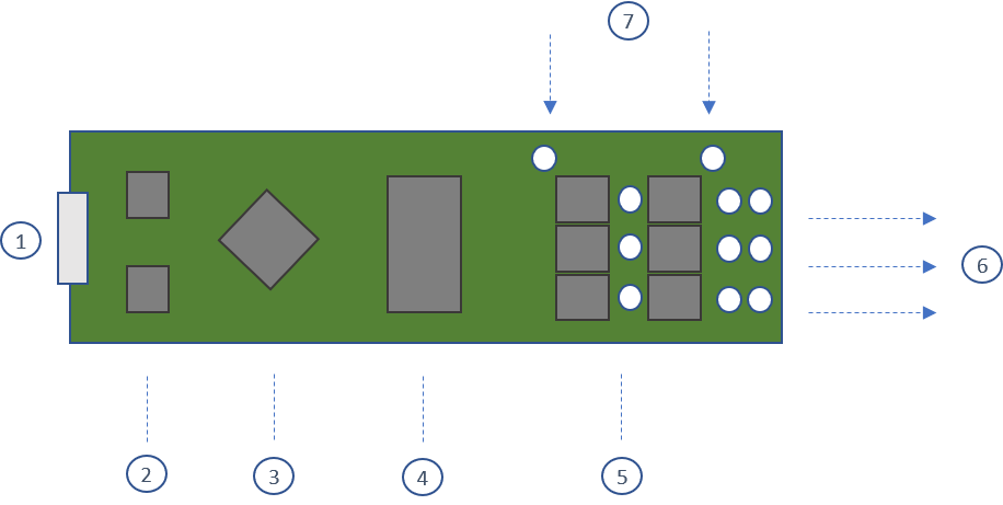
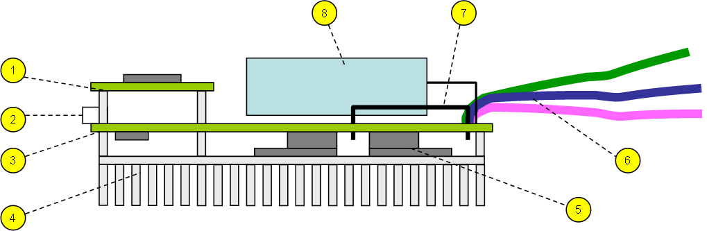
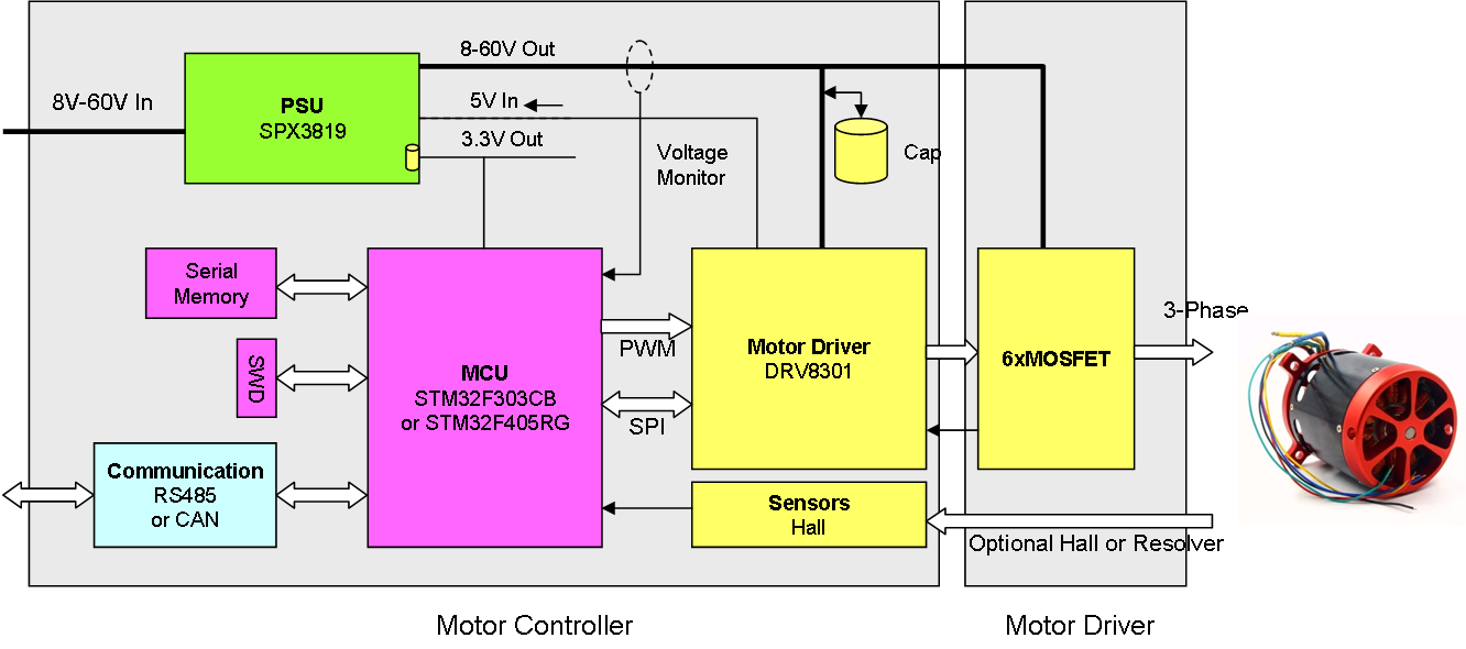
MC3P60V100A will consist of two modules, one controller and one driver. The purpose is to reuse the same controller on various driver designs and MOSFET’s to experiment. I can always make them one board later for project optimization. Testing of this will be a challenge, but let’s worry about larger drivers and higher currents later.

Thank you for Reading! 

Motor Controllers

Just a list of my designs targeting motors with new names so I can keep them apart.

Name Voltage Ampere Driver Type
MC2P12V1A 12V 1A DC Motor controller.
MC3P28V2A 28V 2-2.5A 3-Phase micro controller.
MC3X60V3ACAN 60V 2.5-3.5A New 3-Phase, 2-Phase or 3x Solenoid driver. Previously called MC3X3ACAN.
MC4X24V15A 24V 15A (21A) Stepper, 3-Phase, 2x 2-Phase or Solenoid Driver. This was previously called MC4X15A.
MC3P60V100A 60V 100A New 60V 100A Monster 3-phase design.
MC3S12V1A 12V 1A 3 x 5.wire Stepper Controller
MC8X2P12V1A 12V 1A 8x DC Motor Controller (Raspberry PI Hat)

RS485 is the default interface, if I use something else I will add a post-fix. I will adapt as we go, the only purpose is to avoid using “3 sentences” to explain what controller I write about.

New 60V 100A BLDC Controller

I have so many motor controller designs that I need to give them names, so I use MC + <driver type> + <Max Voltage> + <Max Current>. MC2P60V100A means 3-Phase, 60V (8-60V in this case) and 100A currents. The drawing below is an early draft.


I decided to use DRV8301 or DRV8302. These are dedicated 3-Phase gateways with build in current sensors, Gate drivers and a 5V DC/DC. It is rated 8V to 60V and as MOSFET’s are external we can basically create what we want. DRV8301 uses a SPI interface, while DRV8302 uses separate pin’s. I have written articles about DRV8301 before. The target is larger 12-60V motors like the ones below. I have set the target 100A continuous as I believe that is achievable, meaning I target up to 5KW motors. I do however consider making a separate controller and driver board so I can reuse the controller for different drivers.

I toy around with using STM32F303 or STM32F405, but I will also consider TI Piccolo if I can find a free, working toolchain solution. I have one of their kits with DRV8301 around, but their tool-chain is Code Composer that need (or needed) license. So I assume I will default to STM32 again, but I will see if I can get that dev-kit started.

This is an outrunner with max 60V and 85A. Capable of 5KW and support Hall Sensors.

This one comes in many variants, but it is a Large BLDC designer for drones. This is 24V and ca 40A at max, but I have seen them with higher effects.


MC4X15A Revision 1.1

The Half H-Bridge channels are working very well. I initially had some issues with IR2101 as I do not have pull-up’s. but moving to IR2103 this one have logic to prevent short-cut. This is however a weakness, so I need to add a pull-down resistor so I know the state of the MOSFET before the MCU starts. I will have a New batch of IRF7862 in a few days, this time from Arrow so I can continue testing.

The 0.33F Super-cap have proven it’s worth. It absorb spikes and keep the MCU alive for several seconds after a power down, giving us more than plenty time to detect power glitches.

It is a few mechanical things. I want to move on to micro JST connectors to save some space. It is also a bit tight between the screw connector and the Shunt’s, so I need an extra mm there. I am also looking into using a wired Shunt. I also need to change the drill holes to support the heat-sink I am using and I want to change how I mount capacitors.

The only remaining challenge is the high side current sensors and Hall Sensors. I might need 5V for both these as I move on. Current sensor is the main challenge. INA210 will only support 26V which is “ok” for this controller as we can limit it to 24V, but I would like a solution that is not so fiddly to put on and support higher voltages. I do however have a stack of INA210 so we can try these a bit more first.

This does however come at a trade-off as I have very little space available and INA210 is rather handy. As mentioned before I am doing high-side current sensor rather than the simpler low-side since this allows me to use each channel independently.

Returning to 5V I could actually replace the AMS1117-3.3 with SPX3819-5.0 and SPX3819-3.3. This is a SO23 package with 0.5A spec and I could use TPS54260 to increase input voltage to 60V and 2.5A for 12V. In fact I would like to change the design to become 60V or at least 48V, but MOSFET’s are limited to 30V.

IRF7862 from Arrow

Looking for a proper source for IRF7862 I realized that none of the sources on AliExpress have sold anything before. And checking Arrow I managed to get them cheaper from there at 0.59 USD each.

I also notice that Pololu makes a H-Bridge based on these they claim deliver 15A without heat-sink. I tested 7A pulsing for a few sec before it started heating up, so will be interesting testing a proper batch.

Again I need to stress that AliExpress is usually a reliable source, but I will double-check with Arrow from now on. But, lets see how this arrive and how I get slammed on P&P and MVA.